00195376-05_SM_D1_D1i_D2_D2i_EN.pdf - 第112页
Service Work PCB conveyor system 4.3.17 Overview of the Electrical Components 112 Service Manual SIPLACE D1/D1i/D2/D2i 4.3.17 4 . 3 . 1 7 O v e r v ie w o f t h e E le c t r ic a l C o m p o n e n t s Overview of the Ele…
Service Work
4.3.16 Laser Light Barrier - Stopper Positions [03039286 -xx] PCB conveyor system
Service Manual SIPLACE D1/D1i/D2/D2i 111
Removal/Installation of complete transmitter module
Removal /installation of receiver module
► Loosen the 2 fastening screws on the large transmit-
ter module (1) and the 3 fastening screws on the
small transmitter module (2). Make sure you do not
lose the O-rings.
► Unthread the connection cable as far as the relevant
conversion board of the conveyor edge.
► Unplug the conversion board of the conveyor edge.
► Rerun the connection cable accordingly and recon-
nect the conversion board on the conveyor edge to
the electrical system.
► Fix the new transmitter module in the original posi-
tion.
► Make sure that the 3 O-rings are placed on the 3 fas-
tening screws.
► Switch the machine on.
► Move the side parts of the conveyor system apart to
maximum width.
► Turn the 3 fastening screws to align the transmitter di-
ode centrally to the receiver. The entire height of the
laser beam must hit the receiver. Please also refer to
the Section Settings.
► Loosen the 2 screws fastening the receiver module
(1).
► Unthread the connection cable as far as the relevant
conversion board of the conveyor edge.
► Unplug the conversion board of the conveyor edge.
► Rerun the connection cable accordingly and recon-
nect the conversion board of the conveyor side to the
electricity supply.
► Fit the new receiver module in the original position.
► Switch the machine on.
► Move the side parts of the conveyor system apart to
maximum width.
► Turn the 2 fastening screws to align the receiver cen-
trally to the transmitter diode. The entire height of the
transmitter diode laser beam must hit the receiver.
Please also refer to the Section Settings.
Service Work
PCB conveyor system 4.3.17 Overview of the Electrical Components
112 Service Manual SIPLACE D1/D1i/D2/D2i
4.3.17
4.3.17 Overview of the Electrical Components
Overview of the Electrical Components
4.3.17.1
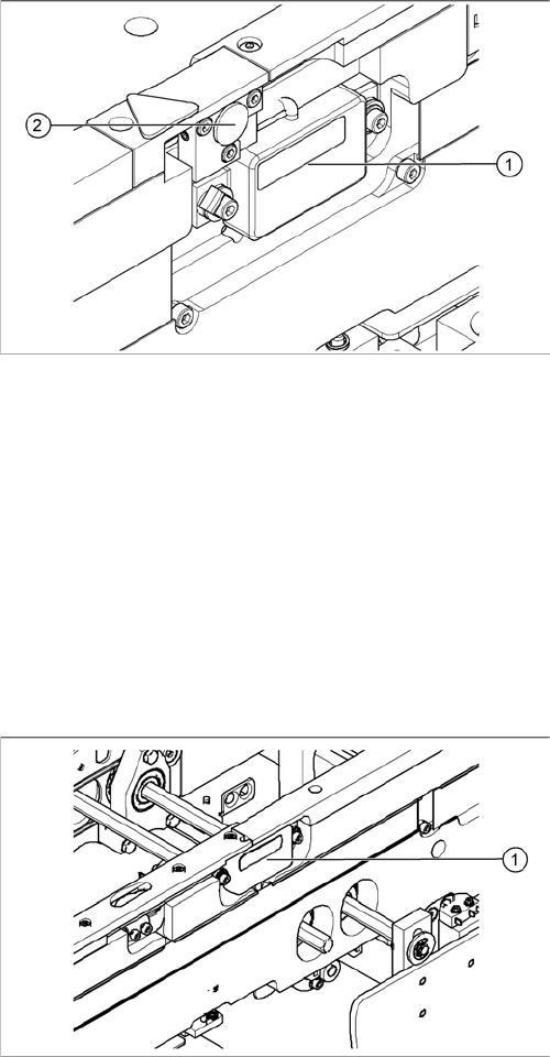
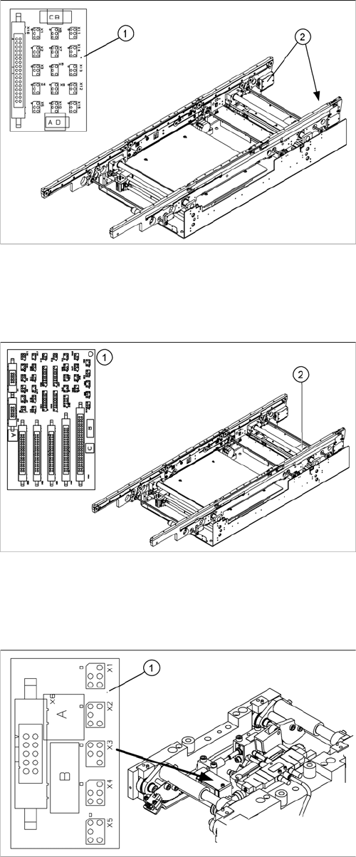
4.3.17.1 Conveyor Side Conversion Board [00359424]
Conveyor Side Conversion Board [00359424]
Overview
4.3.17.2
4.3.17.2 Conveyor Conversion Board [00359426]
Conveyor Conversion Board [00359426]
Overview
4.3.17.3
4.3.17.3 Lifting Table Conversion Board [00362766]
Lifting Table Conversion Board [00362766]
Overview
Legend
1. Conveyor edge conversion board
2. Cover
The conversion boards for the conveyor sides (1) are sit-
uated on the respective conveyor sides, under a cover
(2).
For terminal assignment details, please refer to the cur-
rent version of the detailed circuit diagrams for your
SIPLACE machine.
Legend
1. Conveyor conversion board
2. Cover
The conveyor conversion board (1) is situated in the vi-
cinity of the output conveyor, under the cover (2).
For terminal assignment details, please refer to the cur-
rent version of the detailed circuit diagrams for your
SIPLACE machine.
Legend
1. Lifting table conversion board
2. Cover
The lifting table conversion board (1) is situated on the
lifting table unit, under the cover (2).
For terminal assignment details, please refer to the cur-
rent version of the detailed circuit diagrams for your
SIPLACE machine.
Service Work
4.4.1 Replacing the C&P6/12 Head (D1 D2) C&P6/12 Head
Service Manual SIPLACE D1/D1i/D2/D2i 113
4.3.17.4
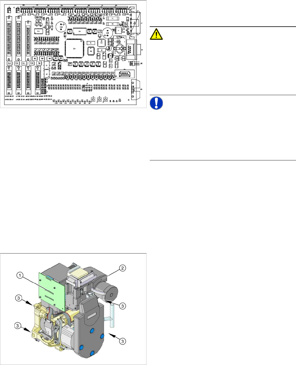
4.3.17.4 Conveyor Control TSP 201 [03043832]
Conveyor Control TSP 201 [03043832]
Overview
4.4
4.4 C&P6/12 Head
C&P6/12 Head
See also
3.5 DLM3 Collect&Place Head [ ➙ 35]
4.4.1
4.4.1 Replacing the C&P6/12 Head (D1 D2)
Replacing the C&P6/12 Head (D1 D2)
Overview
For terminal assignment details, please refer to the cur-
rent version of the detailed circuit diagrams for your
SIPLACE machine.
CAUTION!
Before removal
Before removing the assembly, perform data backup of
the TSP machine data in the SITEST menu "Conveyor –
Machine Data".
After replacing the assembly, restore the machine data in
the same menu.
NOTICE!
Firmware
After replacing the assembly you may need to perform a
firmware download (possible at any time in SITEST from
SC/MC 603.xx).
You may wish to contact SIPLACE service team regard-
ing this work.
Legend
1. Illumination controller
2. Vacuum distributor with vacuum measuring board
3. 4 x fastening screws
Item numbers
C&P head DLM3 with 12 segments (C&P12 head)
▪ Complete, with sleeves [03041228-xx]
▪ Without sleeves [03047768-xx]
C&P head DLM3 with 6 segments (C&P6 head)
▪ Complete, with sleeves [03041229-xx]
▪ Without sleeves [03048341-xx]