00195376-05_SM_D1_D1i_D2_D2i_EN.pdf - 第106页
Service Work PCB conveyor system 4.3.13 Replac ing the Cylinder Switch for the Adjustment Unit [03040796-xx] 106 Service Manual SIPLACE D1/D1i/D2/D2i Removal/Installation ► Move the PCB conveyor to the position which giv…
Service Work
4.3.13 Replacing the Cylinder Switch for the Adjustment Unit [03040796-xx] (applicable to modular PCB conveyor only) PCB conveyor system
Service Manual SIPLACE D1/D1i/D2/D2i 105
Removal/installation
4.3.13
4.3.13 Replacing the Cylinder Switch for the Adjustment Unit [03040796-xx] (applicable to modular PCB conveyor only)
Replacing the Cylinder Switch for the Adjustment Unit [03040796-xx] (applicable to
modular PCB conveyor only)
Overview
The cylinder switch on the adjustment unit cylinder should operate when the adjustment unit pin is
pushed out by the pneumatic cylinder and therefore connected to the conveyor side. This signal enables
the width adjustment motor.
► Move the PCB conveyor to the position which gives
you best access to the adjustment system.
► Move the Y gantries into the area outside the PCB
conveyor.
► Switch off the machine and secure it to prevent unau-
thorized reactivation.
► Switch off the compressed air supply.
► Position the width adjustment belt of the adjustment
unit so that the solenoid valve can be easily ac-
cessed.
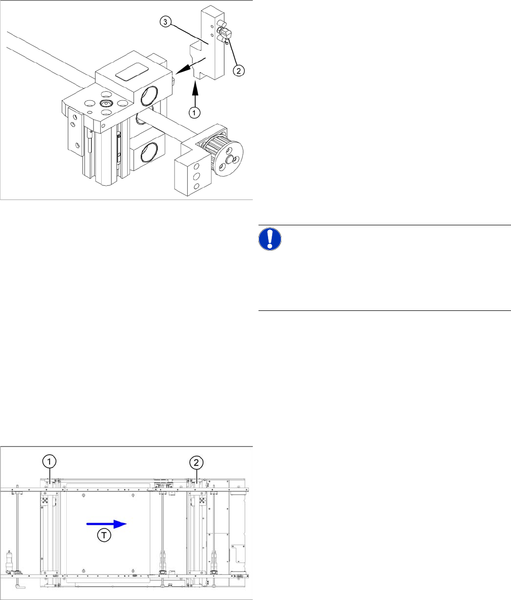
► Remove the compressed air connections (2).
► Loosen the two fastening screws and remove the so-
lenoid valve (3) from the short-stroke cylinder.
► Unthread the connection cable (1) as far as the rele-
vant assembly tub conversion board and unplug.
NOTICE!
This might be somewhat complicated depending on the
routing of cables inside the machine base.
You may wish to contact SIPLACE service team regard-
ing this work.
► Fit the new solenoid valve (3) and reconnect the sys-
tem to the electrical (1) and compressed air (2) sup-
plies.
Parts
▪ Cylinder switch of width adjustment 1 and 2
[03040796-xx]
Legend
1. Adjustment unit 1
2. Adjustment unit 2
▪ T = transport direction
Service Work
PCB conveyor system 4.3.13 Replacing the Cylinder Switch for the Adjustment Unit [03040796-xx]
106 Service Manual SIPLACE D1/D1i/D2/D2i
Removal/Installation
► Move the PCB conveyor to the position which gives
you best access to the adjustment system.
► Move the Y gantries into the area outside the PCB
conveyor.
► Switch off the machine and secure it to prevent unau-
thorized reactivation.
► Switch off the compressed air supply.
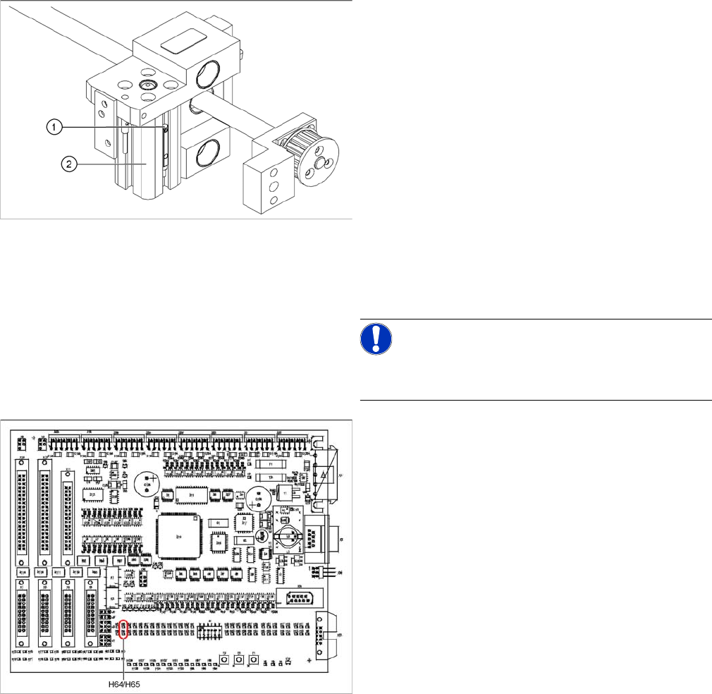
► Loosen the grub screw at the cylinder switch (1) and
push the cylinder switch out of the adjustment unit
guide rail (2).
► Unthread the connection cable as far as the conver-
sion board of the assembly tub.
► Run the connection cable of the new cylinder switch.
► Insert the new cylinder switch into the guide rail.
► Switch the machine on.
NOTICE!
The width adjustment system cylinder switch is set in en-
gaged mode.
TSP201
► Move the width adjustment system until the cylinder
switch switches - LED (H64/H65).
Engage the cylinder - i.e. the cylinders are moved to
the upper limit by the controls.
► Set the cylinder switch so that the LED lights up when
it is in engaged mode.
► Fix the position of the cylinder switch (2) with the grub
screw.
Service Work
4.3.14 Replacing the Proximity Switch for the Adjustment Unit [03040795-xx] (applicable to modular PCB conveyor only) PCB conveyor system
Service Manual SIPLACE D1/D1i/D2/D2i 107
4.3.14
4.3.14 Replacing the Proximity Switch for the Adjustment Unit [03040795-xx] (applicable to modular PCB conveyor only)
Replacing the Proximity Switch for the Adjustment Unit [03040795-xx] (applicable to
modular PCB conveyor only)
Overview
The proximity switch serves as a signal for controlling the pneumatic valve of the adjustment unit. Once
the switching point has been reached, the conveyor edge is connected via the short-stroke cylinder.
Removal/Installation
Parts
▪ Proximity switch for adjustment unit 1 and 2
[03040795-xx]
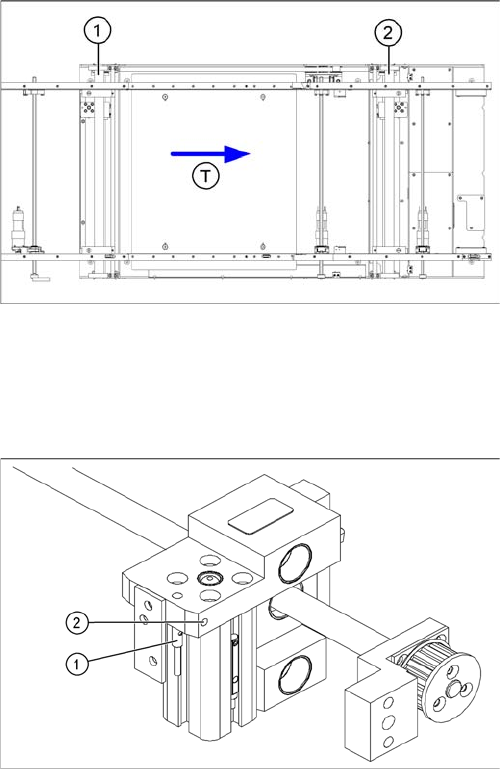
Legend
1. Adjustment unit 1
2. Adjustment unit 2
3. Transport direction
► Move the PCB conveyor to the position which gives
you best access to the adjustment system.
► Move the Y gantries into the area outside the PCB
conveyor.
► Switch off the machine and secure it to prevent unau-
thorized reactivation.
► Switch off the compressed air supply.
► Loosen the grub screw on the clamping device (1)
and unthread the connection cable as far as the con-
version board of the assembly tub.
► Fit the new proximity switch and reconnect the sys-
tem to the electrical system.
► Fix the proximity switch with the grub screw.
► Tighten the grub screw to a torque of 20 Ncm
(+3 Ncm). The proximity switch must be level with the
adjustment unit housing (2).