00195376-05_SM_D1_D1i_D2_D2i_EN.pdf - 第29页
Overview 3.2.3 Power Supply Unit Gantries Service Manual SIPLACE D1/D1i/D2/D2i 29 3.3 3 . 3 G a n t r ie s Gantries Machine gantries (D2 sh own here) Legend The D1 and D2 placement machines are equipped with one or two g…
Overview
Electrical System 3.2.3 Power Supply Unit
28 Service Manual SIPLACE D1/D1i/D2/D2i
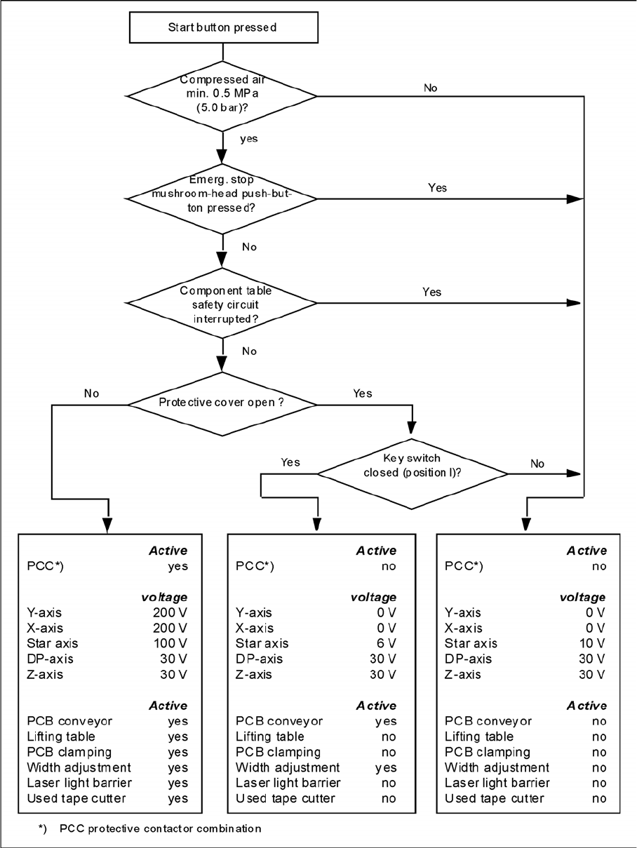
EMERGENCY STOP loops

Overview
3.2.3 Power Supply Unit Gantries
Service Manual SIPLACE D1/D1i/D2/D2i 29
3.3
3.3 Gantries
Gantries
Machine gantries (D2 shown here)
Legend
The D1 and D2 placement machines are equipped with one or two gantries. Using the Y-axis linear drive
and the X-axis belt drives, the gantries position the placement heads in the X and Y direction, above the
feeders and boards (PCBs).
The structure of the gantries makes them torsionally rigid and stable. The precise mechanical movement
of the axes is produced by axis recirculating ball screw units.
High-precision positioning systems determine the positions of the X and Y axes. To do this, the gradua-
tions on metal scales are optoelectronically scanned and the track signals are sent to the axis control in
the control unit.
1 Gantry 1 T Transport direction
2 Gantry 2 (for D2 only)
NOTICE
For an overview of the technical data for D-series machines, refer to "3.1 D-Series - General"
[ ➙ 19].

Overview
Gantries 3.2.3 Power Supply Unit
30 Service Manual SIPLACE D1/D1i/D2/D2i
X-axis drive
A toothed belt is used to directly convert the rotary movement of the X-axis turning motor into a transla-
tory movement of the placement head in the X direction.
Y-axis drive
The translatory movement of the placement head in the Y direction is generated by a linear motor.
Overview of Settings
Description Tools and equipment Values
Belt tension of the X-axis Belt tension measurement
device
D1/D2: 44Hz +/- 1Hz
D3: No longer applies
D4: 53Hz +1/-3
Incremental encoder X/Y Plastic feeler gauge 0.4 mm; Height position on scale coordinated
Distance of encoder/scale 0.4mm
Distance of Y magnets
(Y drive secondary part)
Plastic feeler gauge 0.8 mm; Side/height distance or magnet plates
should be 0.8 mm
X/Y axis dynamics Diagnosis adapter/
SIPLACE axis tester
See section.