00195376-05_SM_D1_D1i_D2_D2i_EN.pdf - 第263页
Settings 6.7.2 Setting the Fixed Conveyor Side (single and dual conveyor ) Modular PCB Conveyor System Service Manual SIPLACE D1/D1i/D2/D2i 263 6.7.2 6 . 7 . 2 S e t t in g t h e F ix e d C o n v e y o r S id e ( s in g …
Settings
Modular PCB Conveyor System 6.7.1 Setting the Tension of the Conveyor Toothed Belt and the Width Adjustment
262 Service Manual SIPLACE D1/D1i/D2/D2i
Legend
6.7.1.1
6.7.1.1 Measuring Points and Belt Tensions for D1/D2 Conveyor
Measuring Points and Belt Tensions for D1/D2 Conveyor
1 Adjustment unit 4 Toothed drive belt for adjusting the width /
measuring the belt tension
2 Recirculating spindle for adjustment unit
3 Width adjustment stepping motor T Transport direction
Width adjustment motor
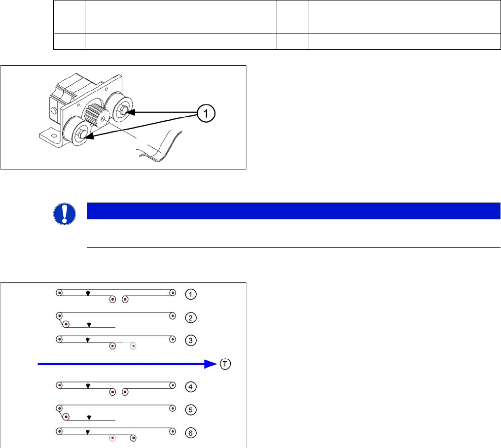
The belt is tensioned by means of cams on the tensioning
rollers. The tensioning rollers are located on the left and
right of the motor.
Legend
1. Loosen the cam shaft on the tensioning roller and set
the belt tension.
NOTICE
The modular conveyor uses different belt lengths. The differing belt tensions between the con-
veyor lanes are due to the different arrangement of hexagonal shafts and deflection pulleys.
Legend
Measuring points (arrows) and measuring values for con-
veyor belt tensions:
Single conveyor or dual conveyor lane 1
1. Input conveyor: 98 +/-10 Hz
2. Processing area: 64 +/- 6 Hz
3. Output conveyor: 100 +/- 10 Hz
Dual conveyor lane 2
1. Input conveyor: 98 +/- 10 Hz
2. Processing area: 69 +/- 7 Hz
3. Output conveyor: 84 +/- 8 Hz
Width Adjustment
▪ Width adjustment Limit switch, 24 +/- 2 Hz
Settings
6.7.2 Setting the Fixed Conveyor Side (single and dual conveyor) Modular PCB Conveyor System
Service Manual SIPLACE D1/D1i/D2/D2i 263
6.7.2
6.7.2 Setting the Fixed Conveyor Side (single and dual conveyor)
Setting the Fixed Conveyor Side (single and dual conveyor)
Two requirements for changing the fixed conveyor sides:
▪ Extra wide conveyor – moves the fixed conveyor side 34 mm outwards.
▪ Widened conveyor – moves the sides of the 2nd conveyor to the limit switch.
Single conveyor control mode (D-series up to 380 mm/HF, X lines up to 450 mm)
6.7.2.1
6.7.2.1 Widening the Conveyor (Flexible Dual Conveyor for Single Conveyor Mode)
Widening the Conveyor (Flexible Dual Conveyor for Single Conveyor Mode)
► In the SITEST conveyor menu Options and Configurations select Change Widening of Conveyor to
widen the conveyor.
► The conveyor rails of conveyor 2 (right side fixed (track 1 left side fix)) are moved to the limits.
► The SITEST SW ask for connecting the lifting tables.
Widening the board conveyor (from its standard width) allows you to use boards up to 380 mm wide.
Widening the board conveyor from the mode "Widened" to the mode "Extra Wide" allows you to place
boards up to a width of 430 mm.
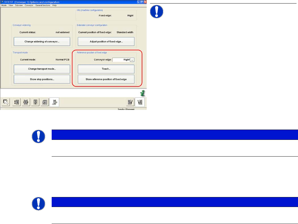
SITEST "Set fixed conveyor side"
NOTICE! The menu Referenzposition feste
Wange is protected with the Siemens Service password.
▪ The fixed conveyor side can be set in SITEST if re-
quired.
▪ If the position taught for the fixed conveyor side is
saved, these values will be used for the function
Move all conveyor edges in standard position.
The default values will be overwritten and will need to
be retaught.
▪ If these dimensions are incorrectly set on the single
or dual conveyor, the PCB reference corner may be
moved, leading to fiducial errors during placement.
NOTICE
In the SR/MC station SW, the fixed conveyor side of all lanes can be adjusted in the conveyor
firmware (flexible). However, this may only be set with the SITEST software.
NOTICE
In the D series machines, you need to remove the clamping rings on the fixed conveyor side in
advance.
Settings
Modular PCB Conveyor System 6.7.2 Setting the Fixed Conveyor Side (single and dual conveyor)
264 Service Manual SIPLACE D1/D1i/D2/D2i
Setting the "fixed conveyor side" in SIPLACE D series
6.7.2.2
6.7.2.2 Connecting the Dual Conveyor Lifting Tables
Connecting the Dual Conveyor Lifting Tables
► Remove the lifting table plate on conveyor lane 2 in PA1 and on lane 1 in PA2.
► Loosen the lockscrew(s) (4) and use a screwdriver to push the hexagonal circlip over the shaft on
lifting table 1.
► Perform lifting table connection for all placement areas (arrangement rotated by 180°.)
NOTICE
The fixed conveyor side should be adjusted only with the SITEST software and the width ad-
justment devices. This ensures that the conveyor runs straight.
NOTICE
This option is only a mechanical necessity when you use the dual conveyor as a single convey-
or. The two lifting tables move parallel when they are connected.
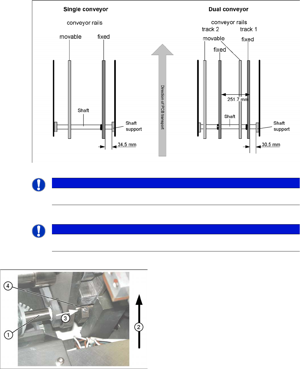
Lifting table
▪ The drive shaft (1) is connected to the piston rod of
the pneumatic cylinder. This shaft is connected to the
shaft of the lifting table for the dual conveyor. The lift-
ing table drive shaft also has an additional rod with a
hexagonal circlip. This pipe is pushed over the shaft
of lifting table 1.
▪ Direction of transport (2).
▪ Direction (3) in which the hollow shaft from lifting ta-
ble 2 (1 in PA 2) is to be moved to lifting table 1 (2 in
PA 2).
▪ Lock screws (4).