00195376-05_SM_D1_D1i_D2_D2i_EN.pdf - 第94页
Service Work PCB conveyor system 4.3.4 Replac ing the Conve yor Toothed Belt [0 0359917-xx] 94 Service Manual SIPLACE D1/D1i/D2/D2i Removal Legend 1. Drive unit with DC geared motor 2. Deflection pulley with slot 3. Conv…
Service Work
4.3.4 Replacing the Conveyor Toothed Belt [00359917-xx] PCB conveyor system
Service Manual SIPLACE D1/D1i/D2/D2i 93
4.3.4
4.3.4 Replacing the Conveyor Toothed Belt [00359917-xx]
Replacing the Conveyor Toothed Belt [00359917-xx]
Overview
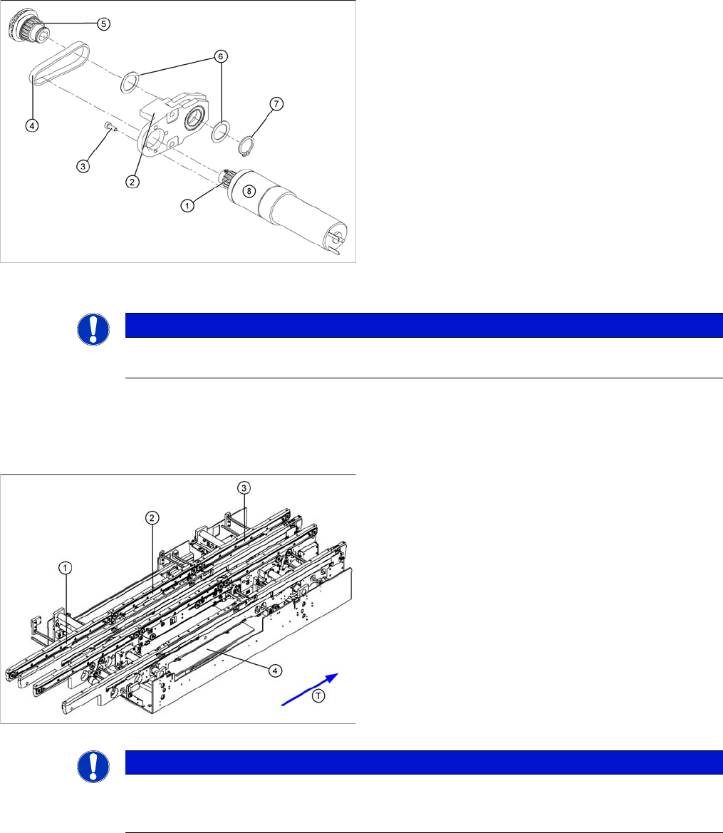
► Place the toothed belt around the toothed disk (5) of
the drive shaft and insert the toothed disk into its
mount.
► Use a rubber mallet to carefully knock the toothed
disk into position.
► Fit the shim rings (6) and the circlip (7).
► Loosely fasten the DC geared motor (8) with the 4 M3
hexagonal socket-head screws (3). The entire width
of the toothed belt must engage at the top and bottom
toothed disks.
► Tension the toothed belt (4) by moving the DC geared
motor in the fastening holes. (See "6.7.1 Setting the
Tension of the Conveyor Toothed Belt and the Width
Adjustment Unit" [ ➙ 261].)
► Fit the complete motor unit.
NOTICE
After the new drive has been installed, check the direction of rotation (polarity) and the conveyor
speed with SITEST.
Parts
▪ [00359917-xx ] Synchroflex toothed belt 1315 long
for input conveyor
▪ [00356850-xx ] Synchroflex toothed belt 1500 long for
placement area
▪ [00364847-xx ] Synchroflex toothed belt 1160 long for
output conveyor
Legend
1. Input belt
2. Placement area
3. Output belt
4. Lifting table
NOTICE
The following diagrams apply to the standard conveyor system (fixed side - right). Depending
on the conveyor side (left or right), either the hexagon shaft guided block or the DC geared mo-
tor will be fitted.
Service Work
PCB conveyor system 4.3.4 Replacing the Conveyor Toothed Belt [00359917-xx]
94 Service Manual SIPLACE D1/D1i/D2/D2i
Removal
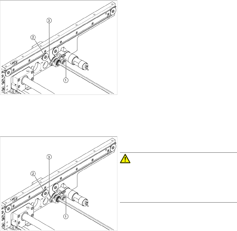
Legend
1. Drive unit with DC geared motor
2. Deflection pulley with slot
3. Conveyor toothed belt
The way in which the conveyor toothed belt is run around
the deflection pulley depends upon the transport area
concerned. Please observe this belt guidance during as-
sembly and disassembly. Please also bear in mind the
following differences during removal and installation:
▪ The drive unit is installed either horizontally or verti-
cally, according to the requirements of the installation
site.
▪ Depending on the conveyor side, either the tape drive
(mount) or a drive unit with DC geared motor will be
mounted.
► Move the PCB conveyor to the position which gives
you best access to the conveyor belt
► Move the Y gantries into the area outside the PCB
conveyor.
► Switch off the machine and secure it to prevent unau-
thorized reactivation.
► Loosen the deflection pulley (2) with the slot and re-
lieve the tension on the conveyor toothed belt (3).
CAUTION!
The deflection pulleys have been assembled with sliding
nuts.
The screw for the deflection pulley should only be loos-
ened! If the screw is removed, the sliding nut will fall be-
hind the conveyor cheek side cover. You then need to
dismantle the cover to retrieve the nut.
► If the drive unit is installed, remove it Unscrew the
hexagonal shaft from the conveyor frame.
► If the tape drive (hexagon shaft guided block) (1) is in-
stalled, remove the 3 fastening screws.
► Carefully pull off the tape drive (hexagon shaft guided
block) or drive unit (1), while also gently unthreading
the conveyor toothed belt (3) through the opening in
the conveyor side.
Service Work
4.3.5 Replacing the Lifting Table Unit [00358653] PCB conveyor system
Service Manual SIPLACE D1/D1i/D2/D2i 95
Installation
4.3.5
4.3.5 Replacing the Lifting Table Unit [00358653]
Replacing the Lifting Table Unit [00358653]
Parts
▪ Lifting table unit for single conveyors [00358653-xx]
▪ Lifting table unit for dual conveyors [00358654-xx]
Overview
CAUTION!
Do not damage the toothed belt!
The toothed belts must not be stretched or kinked!
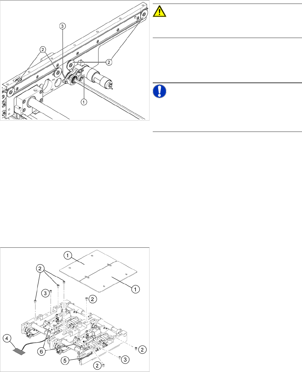
► Feed the new conveyor toothed belt (3) into the drive
unit and weave it round the deflection pulleys (2).
► Insert the tape drive (mount) or drive unit (1) with the
conveyor toothed belt (2) and fasten.
NOTICE!
When replacing the belt on the passive side (tape drive
without drive unit), set the track width to 50 mm. The
tape drive must be aligned towards the active side, allow-
ing smooth axial movement of the hexagonal shafts.
► Tighten the fastening screws.
► Adjust the belt tension. (See "6.7.1 Setting the Ten-
sion of the Conveyor Toothed Belt and the Width Ad-
justment Unit" [ ➙ 261].)
Replacing the lifting table unit (example of dual conveyor
shown)
Legend
1. Lifting table plates
2. 6 x fastening screws for lifting table (M8 x 100) (4 x
for single conveyors)
3. 2 x fastening screws for the lifting table (M8 x 50)