00195376-05_SM_D1_D1i_D2_D2i_EN.pdf - 第150页
Service Work C&P6/12 Head 4.4.19 Replacing the RSF Digital Rotary Encoder (DP Axis) [00335990- xx] 150 Service Manual SIPLACE D1/D1i/D2/D2i Installation ► Insert the new rotary encode r and initially fix loosely in p…
Service Work
4.4.19 Replacing the RSF Digital Rotary Encoder (DP Axis) [00335990-xx] C&P6/12 Head
Service Manual SIPLACE D1/D1i/D2/D2i 149
Installation
See also
4.4.4 Replacing the Intermediate Distributor [ ➙ 119]
4.4.2 Removal/Installation of Head Front Part [ ➙ 115]
4.4.17 Replacing the Star [ ➙ 144]
6.5.9 Determining the Zero Point Correction for the Star Axis of the C&P Head [ ➙ 238]
4.4.19
4.4.19 Replacing the RSF Digital Rotary Encoder (DP Axis) [00335990-xx]
Replacing the RSF Digital Rotary Encoder (DP Axis) [00335990-xx]
Removal
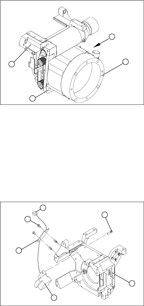
► Place the star motor onto the front part of the C&P
head, so that the star drive connection cable points to
the position marked (A).
► Fix the star drive in place with the four M5x16 hexa-
gon socket-head screws (2).
► Fit and adjust the star. (See zero point correction.)
► If you are unable to adjust the zero point correction
correctly, loosen the 4 star motor screws and rotate
the star motor in the required direction, within the
tightening tolerance.
► Fit the front part of the C&P head.
A
1
3
2
1. Front section of C&P head
2. RSF digital rotary encoder 12/DLM3
3. 2 x M2.5x8 hexagon socket-head screws
4. RSF board, type 950
5. 2 x M2.5x4 hexagon socket-head screws
6. Plug connector in the slot on the intermediate distrib-
utor
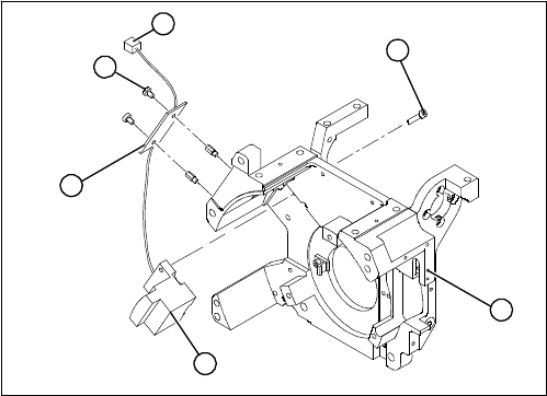
► Dismantle the front part of the C&P head.
► Remove the black blanking cap over the RSF board
(4).
► Remove the plug connector (6) from the slot on the
intermediate distributor.
► Loosen the two M2.5x4 hexagon socket-head screws
(5) for fixing the RSF board.
► Dismantle the handle of the C&P head.
► Loosen the two M2.5x8 hexagon socket-head screws
(3) and remove the digital encoder.
1
6
5
4
3
2
Service Work
C&P6/12 Head 4.4.19 Replacing the RSF Digital Rotary Encoder (DP Axis) [00335990-xx]
150 Service Manual SIPLACE D1/D1i/D2/D2i
Installation
► Insert the new rotary encoder and initially fix loosely
in place with the two M2.5x8 hexagon socket-head
screws (3).
► Fit the handle of the C&P head.
► Insert the sleeve into the star and turn the star, with
the sleeve, until it reaches the rotary encoder.
► Fix the star in this position using the gauge for the
star.
1
6
5
4
3
2
Service Work
4.4.19 Replacing the RSF Digital Rotary Encoder (DP Axis) [00335990-xx] C&P6/12 Head
Service Manual SIPLACE D1/D1i/D2/D2i 151
See also
4.4.2 Removal/Installation of Head Front Part [ ➙ 115]
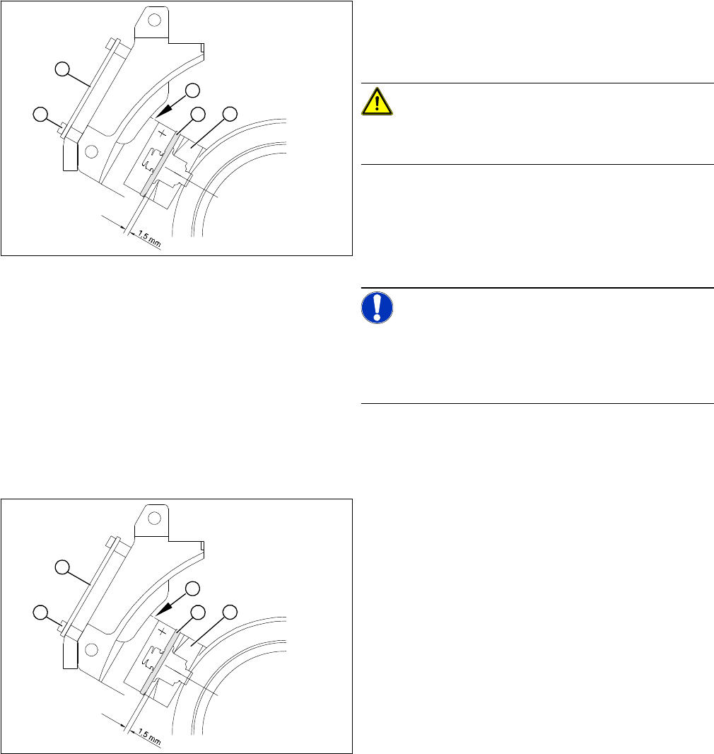
► Adjust the rotary encoder, so that the distance be-
tween the rotary encoder window and the incremental
disk on the sleeve is 1.5 mm.
Proceed as follows:
CAUTION!
Sensitive component!
RISK OF BREAKING THE INCREMENTAL DISK
► Carefully push the tapered end of the test probe be-
tween the window of the incremental encoder (1) and
the incremental disk (2).
► Loosen the fixing screws for the incremental encoder,
if you can not push the test probe in easily.
NOTICE!
The test probe has a blunt and a tapered end. Only push
the tapered end of the test probe between the incremen-
tal encoder and incremental disk of the sleeve, to avoid
scratching the disk and thus causing counting errors.
► Carefully push the rotary encoder towards the incre-
mental disk and along the stop edge (A) until the test
probe lies flat against the incremental disk (2) and the
window of the rotary encoder (1).
► Fix the rotary encoder in place using the two M2.5x8
hexagon socket-head screws.
► Carefully pull the test probe out of the gap.
► Remove the gauge for the star.
► Remove the sleeve from the star.
► Use the two M2.5x4 hexagon socket-head screws (4)
to fasten the RSF board (3).
► Connect the plug connector to the slot on the interme-
diate distributor.
► Place the black blanking cap over the RSF board.
► Fit the front part of the C&P head.
► Test the function of the rotary encoder to make sure
that it is working correctly.
A
1
4
3
2
A
1
4
3
2