00195376-05_SM_D1_D1i_D2_D2i_EN.pdf - 第210页
Settings Gantries 6.2.3 PCB Boards on the Gantry 210 Service Manual SIPLACE D1/D1i/D2/D2i 6.2.3.2 6 . 2 . 3 . 2 V is io n P r o c e s s o r B o a r d ( D ig it a l) Vision Processor Board (Digital) 6.2.3.3 6 . 2 . 3 . 3 …
Settings
6.2.3 PCB Boards on the Gantry Gantries
Service Manual SIPLACE D1/D1i/D2/D2i 209
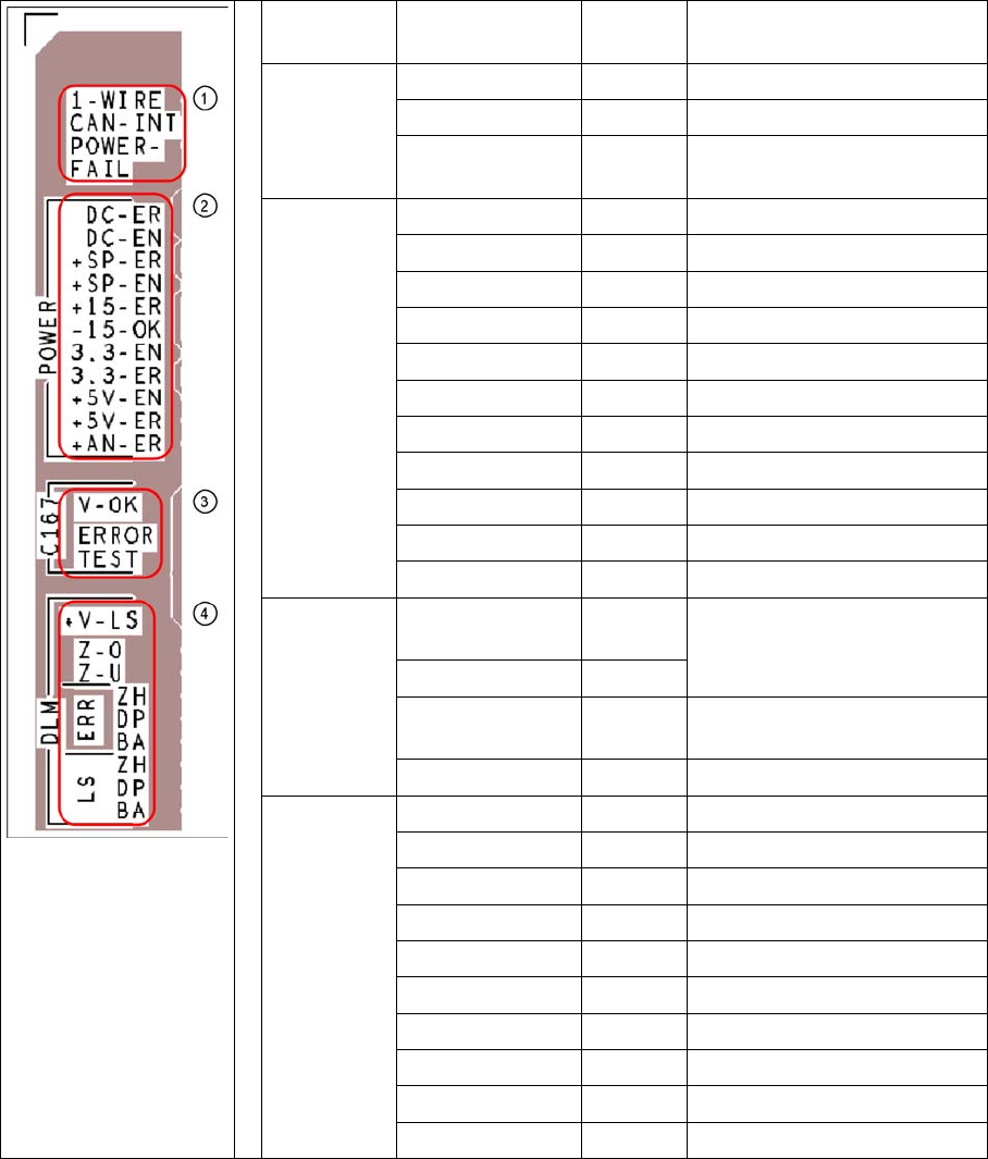
Description of LEDs on the Gantry Head Distributor
SM = stepping motor
Key PCB labeling LED sta-
tus
Description
1
CAN signal
1-WIRE Not in use
CAN-INT OFF not used
POWER-FAIL OFF Error +24 V power supply
(from the main machine)
2
Current sup-
ply
DC-ER OFF Error DC/DC converter
DC-EN ON Enable DC/DC converter
+SP-ER OFF Error +5V track encoder
+SP-EN ON Enable +5V track encoder
+15-ER OFF Error +15V
-15-OK ON -15V is OK
3.3-EN ON Enable +3.3V digital
3.3-ER OFF Error +3.3V digital
+5V-EN ON Enable +5 V digital
+5V-ER OFF Error +5V digital
+AN-ER OFF Error analog supply C167
3
Head
processor
V-OK ON
(green)
Internal voltage monitoring of
eSW
V-OK OFF
ERROR OFF
(red)
Error eSW
TEST Flashes Timer eSW in operation
4
LEDs
C&P head
functions
+V-LS ON OK + 15V light barrier
+V-LS OFF Error +15V light barrier
Z-O ON Z-axis is up
Z-U ON Z down has switched
ERR-ZH OFF Overload SM pickup
ERR-DP OFF Overload SM rotary axis
ERR-BA OFF Overload SM reject
LS-ZH ON Light barrier SM pickup
LS-DP ON Light barrier SM rotary axis
LS-BA ON Light barrier SM reject
Settings
Gantries 6.2.3 PCB Boards on the Gantry
210 Service Manual SIPLACE D1/D1i/D2/D2i
6.2.3.2
6.2.3.2 Vision Processor Board (Digital)
Vision Processor Board (Digital)
6.2.3.3
6.2.3.3 CAN 16 Bit Processor Board (TQ Module)
CAN 16 Bit Processor Board (TQ Module)
Description of 7-segment display (normal operation "." flashes):
▪ After switch ON the machine " 0 " appears on the display
▪ Display "b" --> BIOS was started.
▪ Display flashes alternatively between "b" and "." --> no application available or unable to start appli-
cation.
▪ Display " -I " and " I- " application was loaded.
▪ "." flashes on the display --> ready for operation.
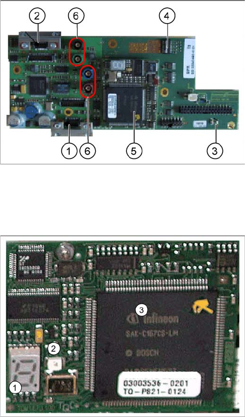
Vision processor board
Legend
1. X8 Connector for illumination and video signals of
PCB camera
2. X3 Connector for illumination and video signals of
component camera
3. LEDs P15V - 15Volt / Vcc - power supply of Vision
board
4. DIP switch for gantry configuration (switch configura-
tion, see section)
5. CAN processor 16 Bit to TQ module
6. Connector X22 - X24 connectors for the video cable
to the trailing cable
The Vision processor board is mounted on the gantry
head distributor board. This PCB is used for all four gan-
tries.
The 16 BIT CAN processor is used for various different
functions in the following units:
(see Chapter Communication and Control)
▪ Vision board, communication and control via the CAN
Bus to the Vision computer.
▪ Gantry head distributor, control of head processes
and vacuum
Legend
1. 7 Segment display
2. LED for manual RESET of processor
3. 16 Bit processor

Settings
6.3.1 Checking the Zero Pulse Signal Track Signals and Zero Pulse
Service Manual SIPLACE D1/D1i/D2/D2i 211
6.2.3.4
6.2.3.4 Checking the DIP Switches
Checking the DIP Switches
DIP Switch on Vision Board
* Not all gantries may be available, depending on the machine type.
Mechanical Adjustment of the Incremental Encoder
The incremental encoders (read units) at the X and Y axes are mechanically set to a distance of 0.4 mm
+/- 0.1 mm and at the marked height to the incremental scale.
See also "4.2.8 Replacing the X-Axis Incremental Encoder (Read Head) [03047215S-xx]" [➙75] for the
diagram "casting marks on the incremental encoder".
6.3
6.3 Track Signals and Zero Pulse
Track Signals and Zero Pulse
6.3.1
6.3.1 Checking the Zero Pulse Signal
Checking the Zero Pulse Signal
The following description is only needed to check the electrical functions of the incremental encoder.
However, if the incremental encoder has been correctly fitted (mechanically), the unit should work with-
out errors.
S Setting for gantry* Comments
1 2 3 4
1 OFF OFF OFF OFF Boot mode - CAN processor 16
Bit via connector X11
2 OFF OFF OFF OFF Reset - CAN processor 16 Bit to
subboard
3OFF ON OFF ONP0 - Address switch 1 --> Gantry
4OFF OFF ON ONP1 - Gantry address switch 2
5 OFF OFF OFF OFF WPE - Write protect enable, cur-
rently OFF
6 OFF OFF OFF OFF CAN R - Switch terminator CAN
bus
7ONON ONONTest 1 - CAN 1 MBit/s --> ON
8ONON ONONTest 0 - CAN IDs --> ON
NOTICE
► To set this distance, use one or more small plastic disks with a total thickness of 0.4 mm.
► After setting the incremental scale, check the zero pulse and the track signals along the en-
tire travel range.
NOTICE
From 2007, machines will be equipped with a new incremental encoder (read head) (as in
SIPLACE D4). A larger measuring window allows you to compensate contaminants on the in-
cremental scale (up to approx. 3.5 mm).