00195376-05_SM_D1_D1i_D2_D2i_EN.pdf - 第109页
Service Work 4.3.15 Replacing the Light Barri er s for Transmitter and Receive r Modules [03039283] PCB conveyor system Service Manual SIPLACE D1/D1i/D2/D2i 109 4.3.15 4 . 3 . 1 5 R e p la c in g t h e L ig h t B a r r i…
Service Work
PCB conveyor system 4.3.14 Replacing the Proximity Switch for the Adjustment Unit [03040795-xx]
108 Service Manual SIPLACE D1/D1i/D2/D2i
The switching point is set at the actuator on the conveyor
edge:
► Position the adjustment unit, with the help of the width
adjustment belt, so that the proximity switch can be
easily accessed.
► Place a 4/10mm distance gauge on the adjustment
unit and press this distance gauge against the adjust-
ment unit.
► Push the proximity switch upwards, as far as the stop
and tighten the fastening screw.
NOTICE!
Perform a width adjustment function test at all conveyor
sides.
► Use the SITEST program to calibrate the conveyor
edges.
Service Work
4.3.15 Replacing the Light Barriers for Transmitter and Receiver Modules [03039283] PCB conveyor system
Service Manual SIPLACE D1/D1i/D2/D2i 109
4.3.15
4.3.15 Replacing the Light Barriers for Transmitter and Receiver Modules [03039283]
Replacing the Light Barriers for Transmitter and Receiver Modules [03039283]
4.3.15.1
4.3.15.1 Replacing the Transmitter
Replacing the Transmitter
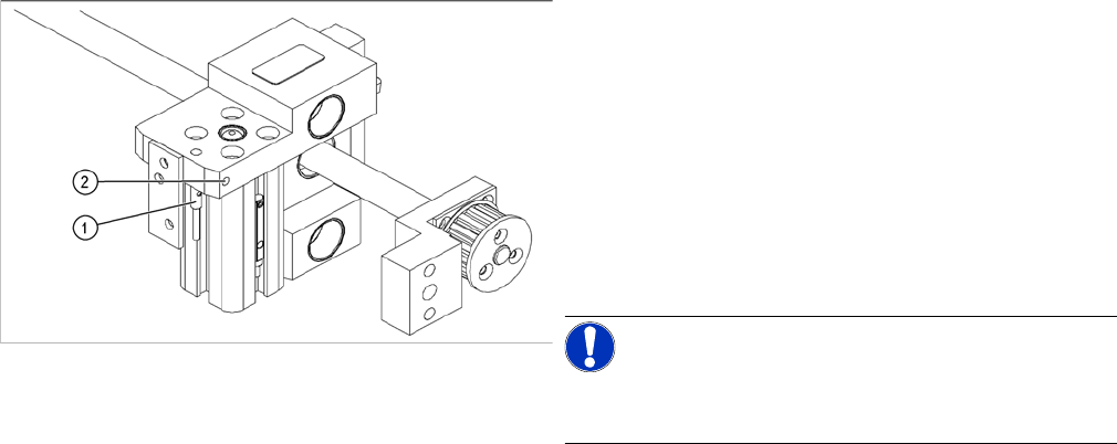
► Dismantle the holder and the transmitter.
► Unscrew the transmitter from the holder.
► Unthread the connection cable as far as the relevant plug in the conveyor edge.
► Unplug the connector plug.
► Rerun the connection cable accordingly and reconnect the plug on the conveyor edge to the electri-
cal system.
► Fix the new light barrier in the original position.
Parts
Please note the different item numbers for the individual
light barriers - these are for the different lengths of the
connection cable.
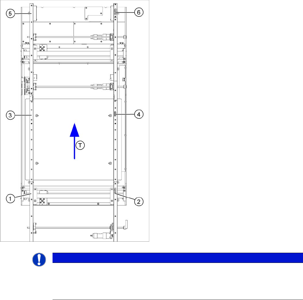
Legend
1. Transmitter at input conveyor [03039283-xx]
2. Receiver at input conveyor [03039269-xx]
3. Transmitter at placement area [03039284-xx]
4. Receiver at placement area [03039270-xx]
5. Transmitter at output conveyor [03039285-xx]
6. Receiver at output conveyor [03039271-xx]
▪ T = transport direction
NOTICE
Important instructions for replacing the light barrier
► When looking in the direction of transport, the transmitter is always on the left.
► Check whether it would be helpful to feed in the new cable with the aid of the old one, at
least in some areas.
Service Work
PCB conveyor system 4.3.16 Laser Light Barrier - Stopper Positions [03039286 -xx]
110 Service Manual SIPLACE D1/D1i/D2/D2i
4.3.15.2
4.3.15.2 Replacing the Receiver
Replacing the Receiver
► Remove the belt guide.
► Unscrew the holder with the receiver.
► Unscrew the receiver from the holder.
► Unthread the connection cable as far as the relevant plug in the cable duct of the conveyor edge.
► Rerun the connection cable accordingly and reconnect the plug in the conveyor edge to the electrical
system.
► Fix the receiver at the holder.
► Fix the holder, together with the receiver, to the base so that the holder lies flat on the base.
► Fit the belt guide and align it parallel to the conveyor rail, with the help of a long board.
► After completing the service work, check the PCB clamping function.
4.3.16
4.3.16 Laser Light Barrier - Stopper Positions [03039286 -xx]
Laser Light Barrier - Stopper Positions [03039286 -xx]
Overview
CAUTION
Align the guide rail parallel to the conveyor edge!
If the guide rail is not aligned parallel, this could result in PCB clamping problems.
Parts
▪ Laser light barrier - transmitter module PA complete
[03039286-xx]
▪ Laser light barrier - receiver module PA [03039272-
xx]
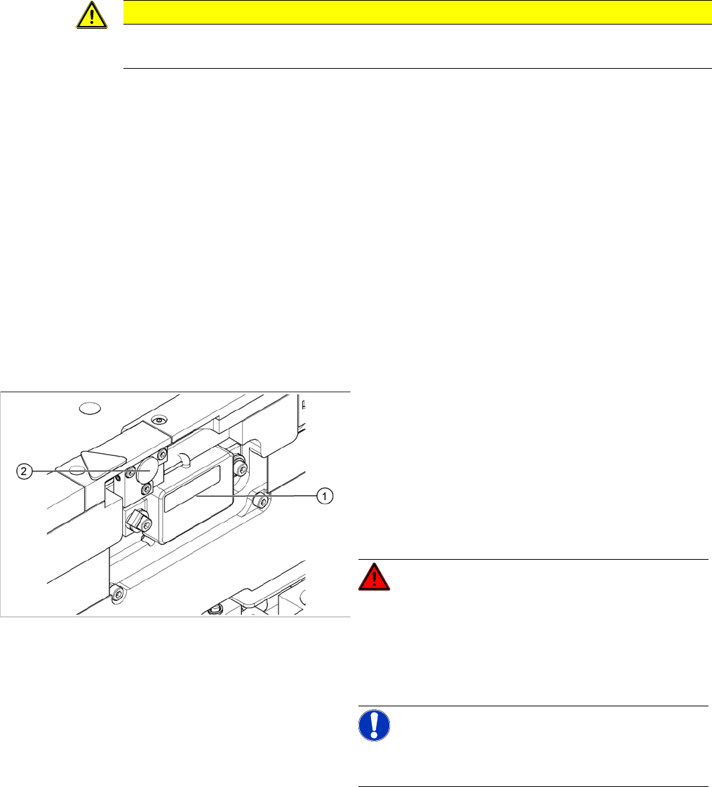
Legend
1. Transmitter module (amplifier) with 2 screws
2. Transmitter module (round laser diode) with 3 screws
DANGER!
The laser light barrier emits class 2 laser beams (from its
transmitter).
You therefore do not require additional protective meas-
ures!
Keep your eyes away from the laser beam!
NOTICE!
After setting the laser light barrier you must check or re-
teach the reference corner!
► Move the PCB conveyor to the position which gives
you best access to the laser light barrier.
► Move the Y gantries into the area outside the PCB
conveyor.
► Switch off the machine and secure it to prevent unau-
thorized reactivation.