00195376-05_SM_D1_D1i_D2_D2i_EN.pdf - 第252页
Settings Pick&Place Head 6.6.7 Calibration of Vacuum Distributor on th e P &P Head 252 Service Manual SIPLACE D1/D1i/D2/D2i 6.6.7.2 6 . 6 . 7 . 2 C h e c k in g t h e Z e r o C a lib r a t io n Checking the Zero …
Settings
6.6.6 Calibrating the Head Height Pick&Place Head
Service Manual SIPLACE D1/D1i/D2/D2i 251
6.6.6
6.6.6 Calibrating the Head Height
Calibrating the Head Height
This menu is used to determine the Z axis zero point correction.
SITEST:
► Select P&P module.
► Select Calibration Functions.
► Select Calibrating the head height.
6.6.7
6.6.7 Calibration of Vacuum Distributor on the P&P Head
Calibration of Vacuum Distributor on the P&P Head
The vacuum distributor is part of the P&P head and creates the vacuum and air blast for the pick up and
placement process. The zero calibration of the vacuum distributor should be performed on initial setup
at the customer site and after replacing the vacuum distributor or P&P head.
If you do not calibrate the vacuum generator, you will have incorrect threshold values for calculating the
"No component on the nozzle or nozzle is dirty" value.
With the aid of the zero calibration the motor of the vacuum generator is positioned into a middle or neu-
tral position, so that there is no vacuum or air blast present at the nozzle.
6.6.7.1
6.6.7.1 Zero Calibration of Vacuum Generator
Zero Calibration of Vacuum Generator
SITEST:
NOTICE
Make sure that the 517 nozzle is on the P&P head and has been entered.
The zero point correction, plus the maximum and minimum travel range for the Z axis will be
correctly set after performing "head height" calibration.
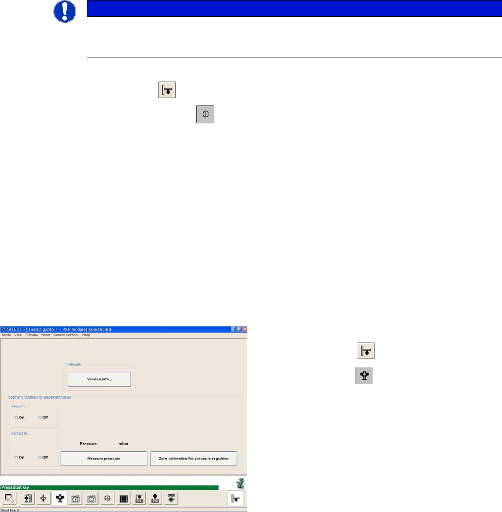
SITEST functions head board functions
► Start the SITEST program.
► Select P&P module.
► Select Head Board to open the adjacent menu.
► Close the nozzle of the appropriate P&P head (e.g.
by sealing it with your finger tip).
Settings
Pick&Place Head 6.6.7 Calibration of Vacuum Distributor on the P&P Head
252 Service Manual SIPLACE D1/D1i/D2/D2i
6.6.7.2
6.6.7.2 Checking the Zero Calibration
Checking the Zero Calibration
SITEST:
► Select P&P module.
► Select Head Board.
► Select Measure Pressure.
The zero calibration is performed with disabled vacuum and air blast (see "6.6.7.1 Zero Calibration of
Vacuum Generator" [ ➙ 251]).
6.6.7.3
6.6.7.3 Calibrating the Closed Vacuum
Calibrating the Closed Vacuum
SITEST:
► Select P&P module.
► Select Calibration Functions.
► Select Calibrate Closed Vacuum.
6.6.7.4
6.6.7.4 Checking the Pressure Tightness of the Vacuum System
Checking the Pressure Tightness of the Vacuum System
► Start SITEST.
► Move the gantry so that you can easily reach the nozzle of the Twin Head with one and the keyboard
with the other hand.
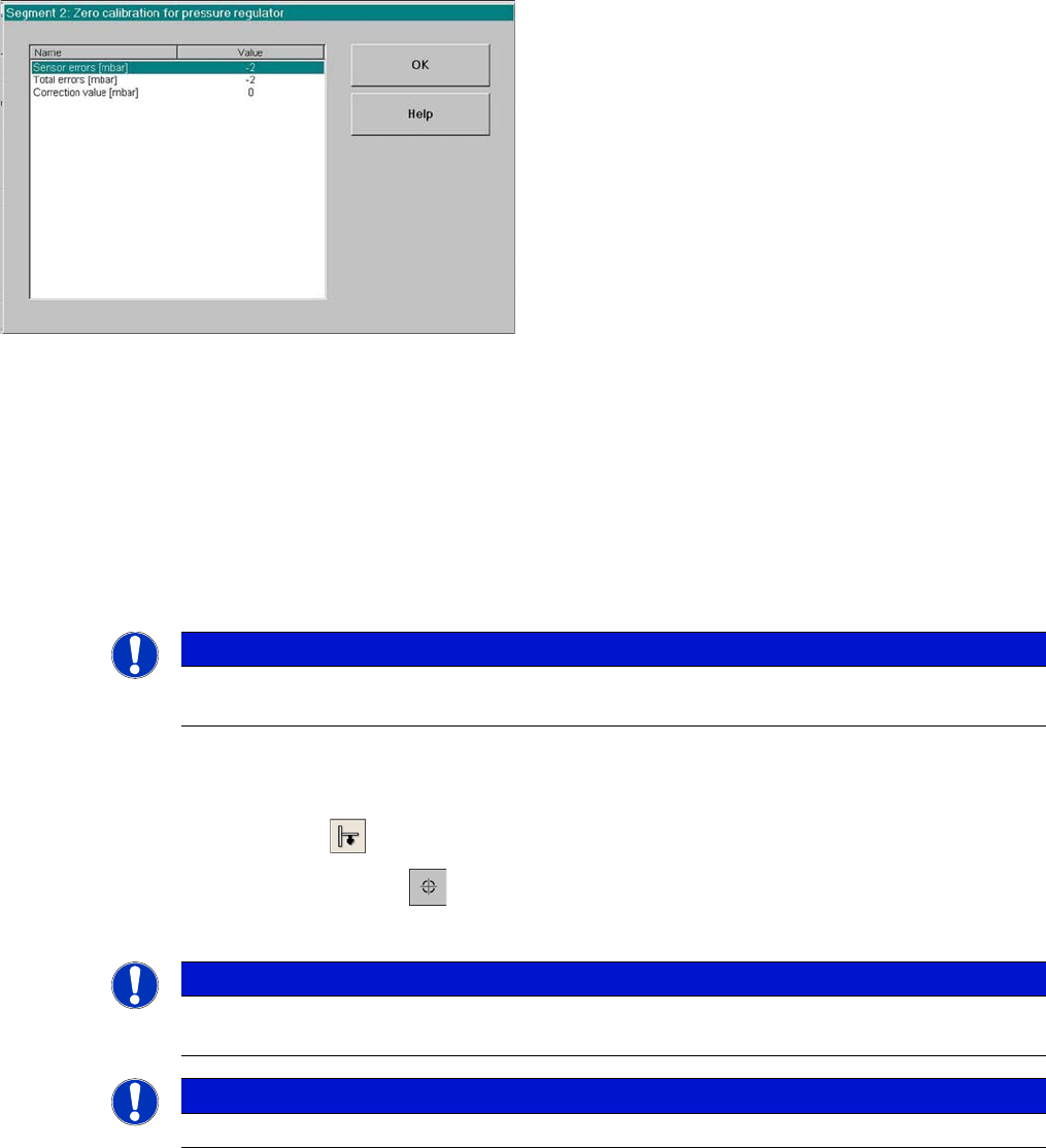
Correction values after zero calibration
► Select Zero calibration pressure regulator
The dialog box on the left shows the correction value
calculated.
► Click on OK.
The correction value will be accepted - now the reference
value equals the ambient pressure.
NOTICE
The pressure deviation to the ambient pressure at 0 - mbar (zero calibration) should not exceed
+/-10 mbar.
NOTICE
The value "Vacuum closed" is measured and stored for the P&P head.
The old and new values are shown in a dialog window.
NOTICE
The term "closed vacuum" corresponds to "threshold value closed".
Settings
6.6.8 Calibrating the P&P Head Pick&Place Head
Service Manual SIPLACE D1/D1i/D2/D2i 253
SITEST:
6.6.7.5
6.6.7.5 Checking the Air Blast
Checking the Air Blast
SITEST:
► Start SITEST. Move the gantry so that you can easily reach the nozzle of the Twin Head with one
and the keyboard with the other hand.
► Select P&P module.
► Select Head Board.
► Switch "on" the air blast.
► Close the nozzle of the appropriate P&P head (e.g. by sealing it with your finger tip).
► You can edit and modify the value for the air blast pressure or leave the standard value.
► Select Measure Pressure.
► The measured value should correspond (approx.) with the given value.
6.6.8
6.6.8 Calibrating the P&P Head
Calibrating the P&P Head
During initial setup or after replacement of a P&P head, the P&P head must be calibrated. This menu
measures the offset between the P&P module and the PCB camera center.
► Place the 517 nozzles manually on the P&P head.
► Make sure that the first nozzle garage is empty and that the component level has been adjusted ac-
cordingly in the nozzle changer. This is necessary for calibration of the pickup height.
► Enter nozzle 517 as the actual nozzle at the P&P head:
SITEST:
► Select P&P module.
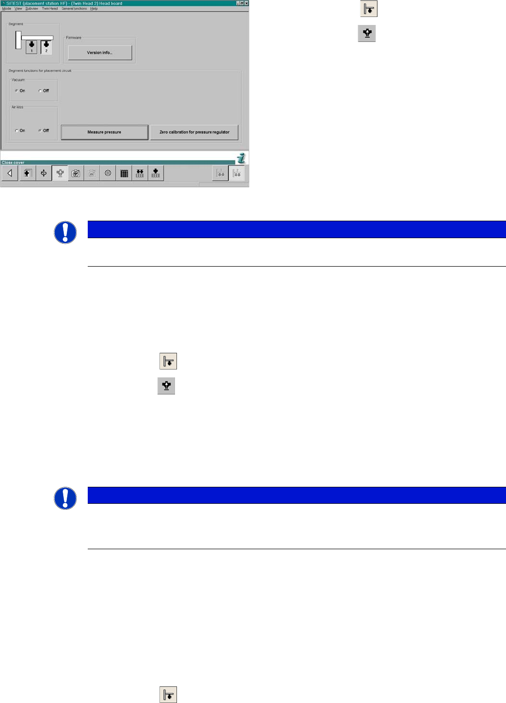
SITEST functions head board functions
► Select P&P module.
► Select Head Board.
► Switch "on" the vacuum and switch the air blast off.
► Close the nozzle of the appropriate P&P head (e.g.
by sealing it with your finger tip).
► Click on Measure Pressure.
► The displayed value should be close to the "Thresh-
old value closed".
NOTICE
The value "vacuum closed" is determined in the Calibrate P&P-Module ==> Calibrating the
closed vacuum menu.
NOTICE
The air blast value can be edited with to a value between 0 and 400 mbar, with the Siemens
Service password.
► Default setting: 400 mbar