00195376-05_SM_D1_D1i_D2_D2i_EN.pdf - 第178页
Service Work Changeover Table 4.6.1 Safety Instructions 178 Service Manual SIPLACE D1/D1i/D2/D2i 4.6 4 . 6 C h a n g e o v e r T a b le Changeover Table 4.6.1 4 . 6 . 1 S a f e t y I n s t r u c t io n s Safety Instructi…
Service Work
4.5.9 Replacing the Air Filter Pick&Place Head
Service Manual SIPLACE D1/D1i/D2/D2i 177
4.5.9.2
4.5.9.2 Replacing the Air Filter (Digital Vacuum Control System) [03047489-xx]
Replacing the Air Filter (Digital Vacuum Control System) [03047489-xx]
Removal/Installation
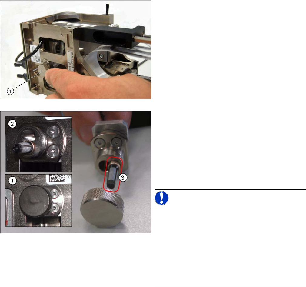
► Open the cover on the left side of TWIN segment 1 (or
right side of TWIN segment 2) and remove the air fil-
ter (1) so that it can be cleaned or replaced.
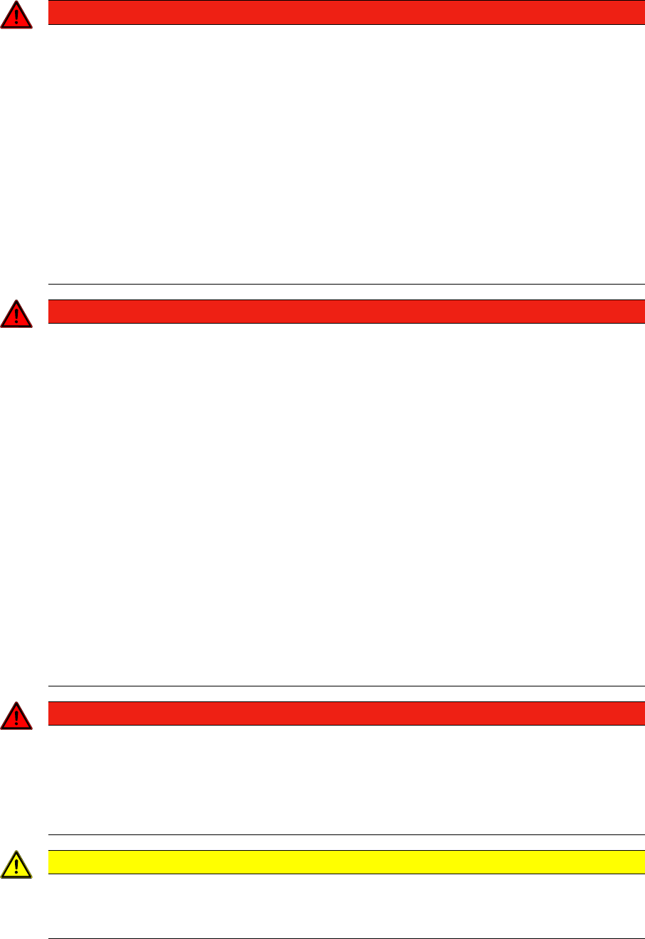
Legend
1. Air filter in installed state
2. Air filter open
3. Replacement filter FE 50 [03047489-xx]
The digital vacuum generator has a thin high-precision
tube in the vacuum supply to the nozzle. Between this
tube and the vacuum connection of the vacuum genera-
tor you will find the air filter (3) which protects the gener-
ator from contaminants introduced via the nozzle.
NOTICE! The lower drilling (when the clamping
screw is on the right) is deep enough to accommodate
the filter (with the cage opening pointing inwards) (2).
The upper drilling is not deep enough to accommodate
the filter. In this case, the filter would be irreparably dam-
aged when the sealed cover (lid with O ring inside) is
screwed on.
This filter unit may ONLY be used in combination with the
digital vacuum generator.
The specified hose volumes will only ensure reliable func-
tion in this case.
► Insert the filter (3) into the drilling (with the brass tube
first) and screw the cover back on to the air filter.
Service Work
Changeover Table 4.6.1 Safety Instructions
178 Service Manual SIPLACE D1/D1i/D2/D2i
4.6
4.6 Changeover Table
Changeover Table
4.6.1
4.6.1 Safety Instructions
Safety Instructions
DANGER
The chapters "Operational Safety“ and "Changeover Tables“ in the operating manual and the
chapter "Operational Safety“ in this service manual take priority.
These SIPLACE machines are powered by 120V / 208V +/- 5% (US version) or 3 x 230V/400V
+/- 5%, 50/60 Hz main voltage supply.
Parts of the system therefore carry dangerously high voltages! In specific modules the voltage
is present inside the machine base even when the main switch is turned off.
Handling the machines improperly or touching parts thereof which conduct high voltage may
result in death or serious physical injury as well as extensive property damage.
► Observe the applicable accident prevention regulations, DIN standards and special safety
codes of your country at all times. DIN EN 60204 must be adhered to during all work inside
the machine base
► The Siemens service engineer is the only person permitted to adjust / change the voltage,
in line with the internal Siemens retrofitting instructions.
DANGER
Risk of limbs being pinched, crushed or severed by the changeover table (see "4.6.1 Safety In-
structions" [ ➙ 178]).
Do not exert any substantial lateral force to the changeover table after it has been disassem-
bled (danger that it might tip over), therefore:
- Do not lean against it and do not brace any items against it.
- Place the changeover table on a horizontal surface and secure it to prevent it from rolling away
by itself.
Once the changeover table has been moved out of the machine, NEVER connect the plugs to
the machine base (= improper use = DANGER!)
Moving the changeover table out of the machine leaves the cutter (etc.) accessible:
This increases the risk of injury on the cutter’s movable or stationary blades even while the ma-
chine is switched off.
NEVER reach into the cutter from below or into the empty-tape duct from above, not even to
resolve a problem (e.g., jammed tape) involving the disassembly of the changeover table.
Risk of pinching and shearing also exists
► At incorrect setting/adjustment of the SMEMA height (setting only permitted by SIEMENS
service technician -> see Siemens internal retrofitting instructions),
► When a feeder module falls over or down,
DANGER
PLACEMENT HEAD CRASH
The Y gantry of all SIPLACE machines must be moved out of the
changeover table area before any table change can be performed.
This must be accomplished before actuating the compressed air switch to raise the table.
Otherwise there is a risk that the placement head may crash!!
CAUTION
Take care when lowering or raising the handle of the changeover table. There is a risk of minor
injuries from the handle, such as pinching or scraping.
► For this reason, always hold the handle with both hands.

Service Work
4.6.2 Preparations for Service Work Changeover Table
Service Manual SIPLACE D1/D1i/D2/D2i 179
4.6.2
4.6.2 Preparations for Service Work
Preparations for Service Work
► Move the relevant changeover table out of the machine. (See operating manual)
► When replacing the bellows cylinder:
Take the feeder modules from the changeover table and place them on a clean surface. In this case,
the tape reels can remain in the container.
► When exchanging the guide castors and fixed castors:
Same steps as above for exchanging the bellows cylinder.
In addition, remove all of the tape reels from the container and put them down in order.
► When replacing the cable for the changeover table and/or the communications unit:
You do not need to dismantle the feeder modules.
4.6.2.1
4.6.2.1 Tools and Equipment
Tools and Equipment
▪ Set of Allen wrenches
▪ Diagonal cutter (for cable tie)
▪ External power supply for changeover table
▪ Extension lead for changeover table
4.6.3
4.6.3 Replacing the Fixed and/or Guide Castors
Replacing the Fixed and/or Guide Castors
Parts
▪ 2x fixed castor [03044881-xx]
▪ 2x double guide castor [03050704-xx]
Removal/Installation
The changeover table is dismantled and prepared, as described in "4.6.2 Preparations for Service Work"
[ ➙ 179].
► Tear down the changeover table and remove the partition plates in the tape container.
► Enlist the aid of a 2nd strong person and place the changeover table on its side (1).
► Undo the screws fastening the fixed castor and/or guide castor to be exchanged (size 6 Allen
wrench: ).
► Insert the new guide castors and/or fixed castors and fix these back into place with 4 hexagon sock-
et-head screws each.
► With the aid of a 2nd strong person, set the changeover table back up.
Secure the changeover table to prevent it from rolling away by itself.
► If you have no further parts to be replaced, perform the appropriate "Final Steps" (see "4.6.6 Final
Steps" [ ➙ 182]).
WARNING
The changeover table needs to be laid on its side to remove the fixed castor and/or guide cas-
tor.
Two people are required for this as the changeover table is very heavy.