00195376-05_SM_D1_D1i_D2_D2i_EN.pdf - 第163页
Service Work 4.5.2 Replacing the Vacuum Contro l System, Filter and Additiona l Volume Pick&Place Head Service Manual SIPLACE D1/D1i/D2/D2i 163 TWIN segmen t 1 front view / TWIN segment 2 rear view ► Op en the thr ea…
Service Work
Pick&Place Head 4.5.2 Replacing the Vacuum Control System, Filter and Additional Volume
162 Service Manual SIPLACE D1/D1i/D2/D2i
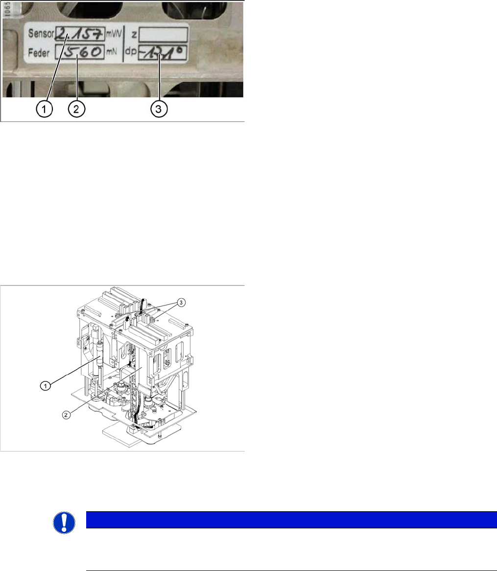
Entering the force values for the new module
4.5.2
4.5.2 Replacing the Vacuum Control System, Filter and Additional Volume
Replacing the Vacuum Control System, Filter and Additional Volume
4.5.2.1
4.5.2.1 Replacing the Vacuum Control System (Version 01 - Analog) [03002566-xx]
Replacing the Vacuum Control System (Version 01 - Analog) [03002566-xx]
Overview
Removal/Installation
► Remove the relevant P&P module from the machine.
► Start the SITEST program and enter the new force
values for this module.
► To do this, select the Twin head axis function in the
SITEST program and activate the appropriate seg-
ment (module).
► Activate the Z axis radio button and select the Param-
eter... button.
► Enter the values for the force sensor adjust value and
the spring bias.
► Use the SITEST program to then calibrate the Twin
Head.
⇨ Head height
⇨ Camera IC
⇨ Head calibration
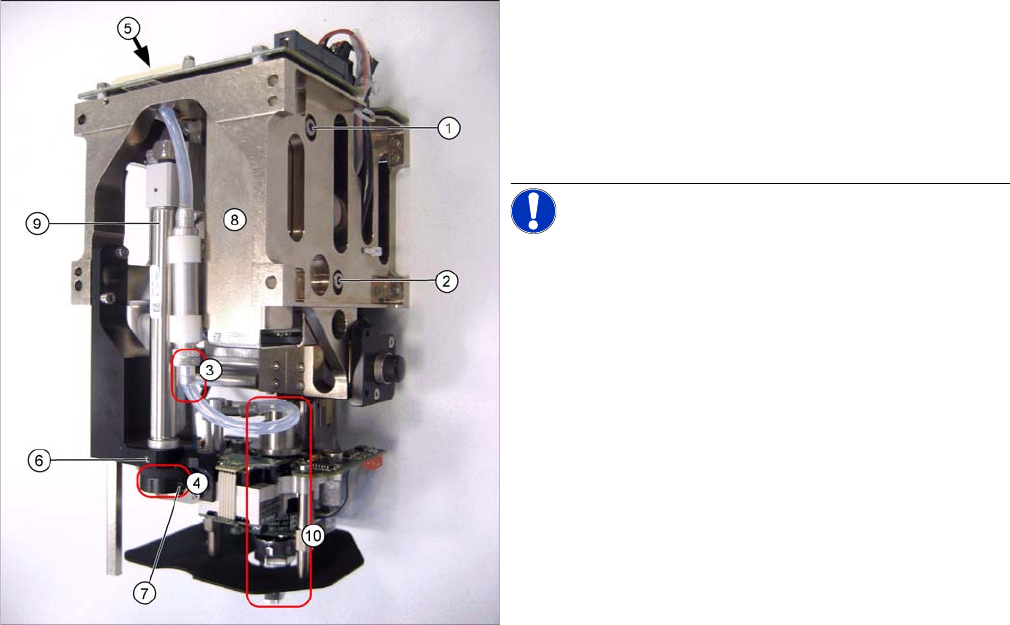
Legend
1. Filter for the vacuum control system
2. Vacuum control system
3. Compressed air connections
NOTICE
The version with analog vacuum control system covers several different variants.
The following example uses the version in which the additional volume is fastened to a holder
on the vacuum control system.
Service Work
4.5.2 Replacing the Vacuum Control System, Filter and Additional Volume Pick&Place Head
Service Manual SIPLACE D1/D1i/D2/D2i 163
TWIN segment 1 front view / TWIN segment 2 rear view
► Open the threaded pin (7) in the stopper (4) of the re-
turn unit.
► Pull the return unit downwards at the stopper, hold
the hexagonal shaft and unscrew the stopper.
► Open the threaded pin (6) on the return unit and turn
the return unit to the side.
NOTICE! This is only required for the analog
vacuum generator. The controller and filter can be re-
moved from the digital vacuum control system without
this step.
► Disconnect the silicone hosefrom the bottom connec-
tion (3) of the additional volume.
► Unscrew the vacuum control system (8) by loosening
the fastening screws at (1) and (2).
► Pull the vacuum control system downwards so that it
can be unplugged from the head main board (5).
► Unthread the vacuum control system next to the re-
turn cylinder (9) and above the DP turning unit (10) on
the Z mechanics.
Service Work
Pick&Place Head 4.5.2 Replacing the Vacuum Control System, Filter and Additional Volume
164 Service Manual SIPLACE D1/D1i/D2/D2i
Installation
► Installation is performed by following the above instructions in the reverse order.
► Perform a complete installation check. (see "4.5.2.3 Installation Check" [ ➙ 166])
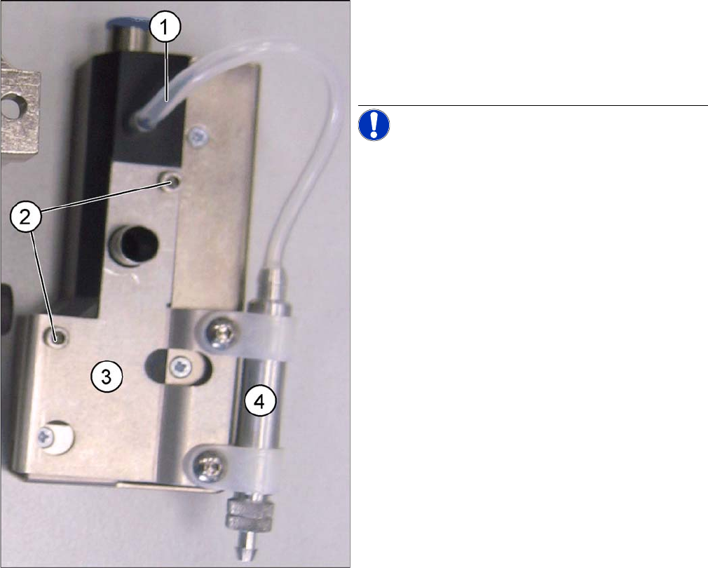
► Disconnect the silicone hose (1) from the vacuum
control system.
► Loosen the two fastening screws (2) and remove the
holder (3) for the additional volume (4) from the vac-
uum control system.
NOTICE! These two drillings (2) mean that the
holder ONLY fits on the analog vacuum control valve.