00195376-05_SM_D1_D1i_D2_D2i_EN.pdf - 第58页
Service Work Electrical System 4.1.5 Replacing the Servo Card 58 Service Manual SIPLACE D1/D1i/D2/D2i 4.1.5 4 . 1 . 5 R e p la c in g t h e S e r v o C a r d Replacing th e Servo Card See also 4.5.8 Replacing the Ser…
Service Work
4.1.4 Replacing the A364 Axis Card Electrical System
Service Manual SIPLACE D1/D1i/D2/D2i 57
4.1.4
4.1.4 Replacing the A364 Axis Card
Replacing the A364 Axis Card
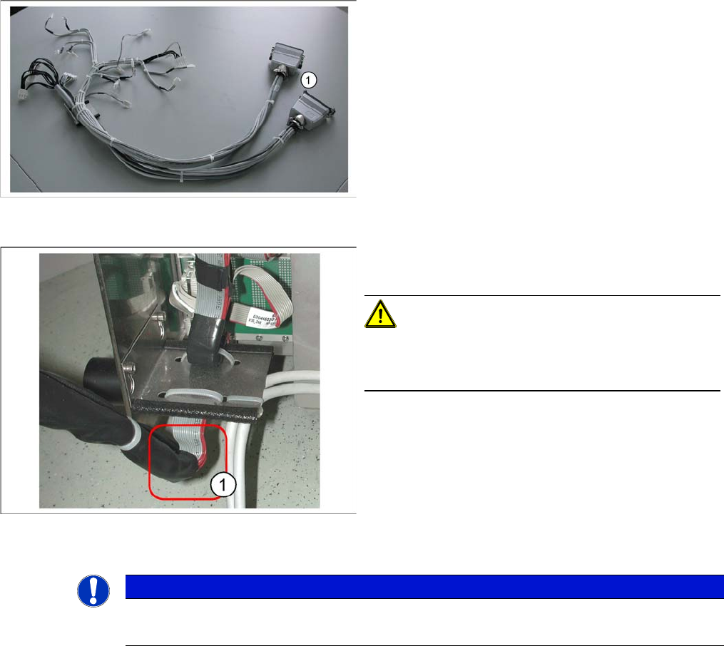
Adapter cable harness
► Connect the Harting connector (1) of the adapter ca-
ble harness to the relevant connection point on the
machine.
► Hook the axis unit back into the guide rail in the ma-
chine. Carefully stow the cables in the machine.
CAUTION!
Make sure you do not damage any cables. Pay particular
attention to the lower part of the flat ribbon cable harness
(1). Make sure this does not rub against any parts.
► Push the axis unit into the machine and fit the protec-
tive cover.
► Switch the machine back on and perform a function
test.
NOTICE
The axis cards may only be replaced by SIPLACE service technicians.
► Contact your local SIPLACE service team.
Service Work
Electrical System 4.1.5 Replacing the Servo Card
58 Service Manual SIPLACE D1/D1i/D2/D2i
4.1.5
4.1.5 Replacing the Servo Card
Replacing the Servo Card
See also
4.5.8 Replacing the Servo Amplifier [00353446] [ ➙ 176]
4.1.5.1
4.1.5.1 Servo Card Positions for SIPLACE D1
Servo Card Positions for SIPLACE D1
Servo cards for D1
4.1.5.2
4.1.5.2 Servo Card Positions for SIPLACE D2
Servo Card Positions for SIPLACE D2
Servo cards for D2
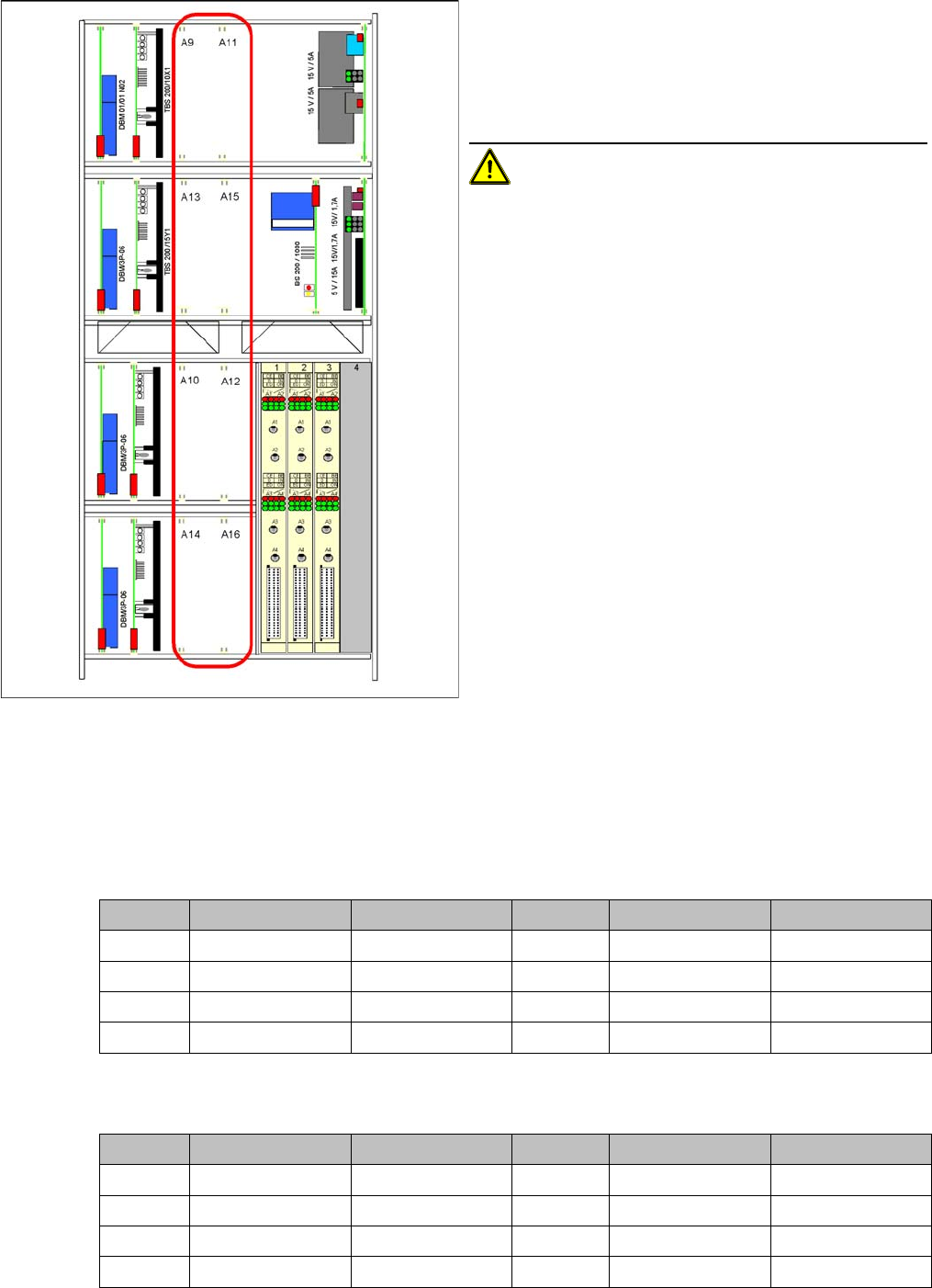
Servo cards in axis unit
Item numbers
▪ Servo board (servo amplifier) for Z axis of P&P head
[00353446-xx]
▪ Servo card for DP axis P&P head [00353447-xx]
Removal/Installation
CAUTION! The TBS servo cards may only be
used for the star axis of the DLM3 head.
► End all placement operations with the machine.
► Switch the placement system off at the main switch.
► Open the axis unit.
► Open the locking bracket and remove the required
servo card, by moving the release lever up and down.
► Insert the new servo card and push the assembly in
(you will feel a slight resistance) until it engages.
► Switch the machine on again.
C&P head P&P head C&P head P&P head
A9 -Z axisA11 Z axis -
A13 -DP axisA15 Star axis -
A10 --A12 --
A14 DP axis - A16 --
Gantry 1 C&P head Gantry 2 C&P head
A9 Star axis A11 Z axis
A13 - A15 -
A10 Star axis A12 Z axis
A14 DP axis (gantry 1) A16 DP axis (gantry 2)
Service Work
4.1.6 Computer Unit - Replacing Parts Electrical System
Service Manual SIPLACE D1/D1i/D2/D2i 59
4.1.6
4.1.6 Computer Unit - Replacing Parts
Computer Unit - Replacing Parts
4.1.7
4.1.7 CAN Bus Terminator Board for Changeover Table [03046863-xx]
CAN Bus Terminator Board for Changeover Table [03046863-xx]
Removal/Installation
Jumper setting for CAN terminator circuit
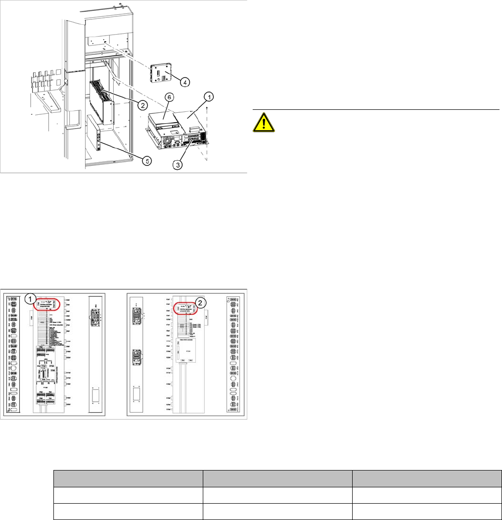
Legend
1. Station computer (Box PC) [03032341-xx]
2. Machine Controller (Micro Box PC) [03047697-xx]
3. Hotlink interface [03032343-xx]
4. Video multicoupler [03040316-xx]
5. USB hub 2.0 [03032344-xx]
6. Portable USB DVD/CD drive [03051205-xx]
CAUTION! If necessary, perform data backup
before replacing any parts.
► Detach all connections to the relevant part and label
these for easier reconnection, later.
► Loosen any fixtures and remove the part.
► Fit the new part by following the above instructions in
reverse order and configure the part, where required.
Legend
1. CAN Bus terminator board - changeover table in main
distributor (transport direction to left)
2. CAN Bus terminator board - changeover table in sub-
distributor (transport direction to right)
► Detach all connections to the board to be replaced.
Label these for easier reconnection, later.
► Remove the board.
► Fit the new board and reestablish all connections.
► Set the jumper on the board according to the relevant
sector, as shown in the following table:
Jumper Subdistributor Main distributor
1ONOFF
2ONON