00195376-05_SM_D1_D1i_D2_D2i_EN.pdf - 第40页
Overview Pick&Place Head 3.5.6 Overview of Settings 40 Service Manual SIPLACE D1/D1i/D2/D2i P&P head – viewed from two sides Legend Overview of Settings 1 Z-axis drive 5 Compressed air connection to rotary axis 2…
Overview
3.5.6 Overview of Settings Pick&Place Head
Service Manual SIPLACE D1/D1i/D2/D2i 39
3.6
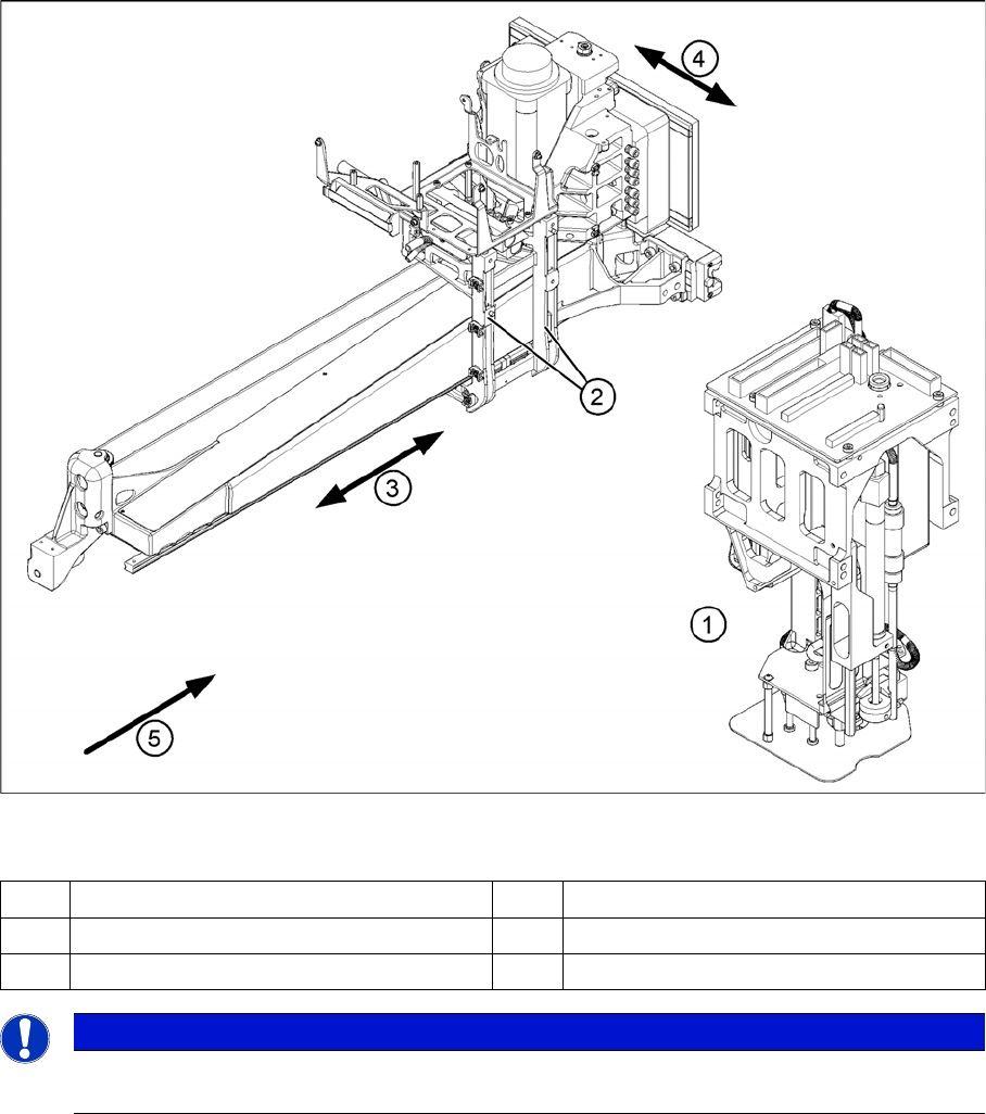
3.6 Pick&Place Head
Pick&Place Head
Legend
1 Pick&Place head (P&P head) 4 Y axis
2 Head mount 5 Transport direction
3X axis
NOTICE
The Pick&Place head (P&P head) is the same as one segment of a Twin Head, at a D3 or X-
series machine.
Overview
Pick&Place Head 3.5.6 Overview of Settings
40 Service Manual SIPLACE D1/D1i/D2/D2i
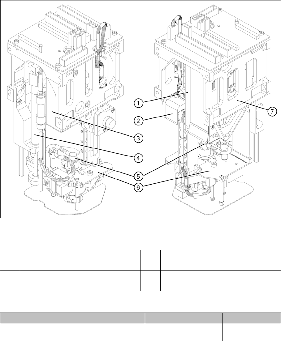
P&P head – viewed from two sides
Legend
Overview of Settings
1 Z-axis drive 5 Compressed air connection to rotary axis
2 Z-axis incremental encoder 6 D-axis drive under the board
3 Vacuum control system 7 Label with Z-axis parameters
4 Return unit
Description Tools and equipment Values
Distance between incremental encoder and incre-
mental scale
Plastic gauge 0.4 mm; 0.4mm
Overview
3.5.6 Overview of Settings Cutter
Service Manual SIPLACE D1/D1i/D2/D2i 41
3.7
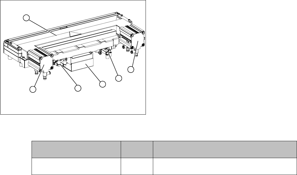
3.7 Cutter
Cutter
Overview
Overview of Settings
Legend
1. Tape cutter, pneumatic
2. Short-stroke cylinder
3. Control unit
4. Solenoid valves
2
4
1
4
3
2
Description Tools and
equipment
Values
Control unit jumper settings - See "6.9.1 Jumper setting on the control unit at the tape
cutter" [ ➙ 278].