00195376-05_SM_D1_D1i_D2_D2i_EN.pdf - 第22页
Overview Electrical System 3.2.1 Axis Unit 22 Service Manual SIPLACE D1/D1i/D2/D2i 3.2.1 3 . 2 . 1 A x is U n it Axis Unit Overview of Settings Axis unit (D2 as example) Legend 1. X-axis brake board, gantry 1 2. X-axis s…
Overview
3.1.4 SIPLACE D4 Electrical System
Service Manual SIPLACE D1/D1i/D2/D2i 21
3.2
3.2 Electrical System
Electrical System
Position of the modules
Position of the modules
Legend
See also
3.3.2 Overview of Boards [ ➙ 33]
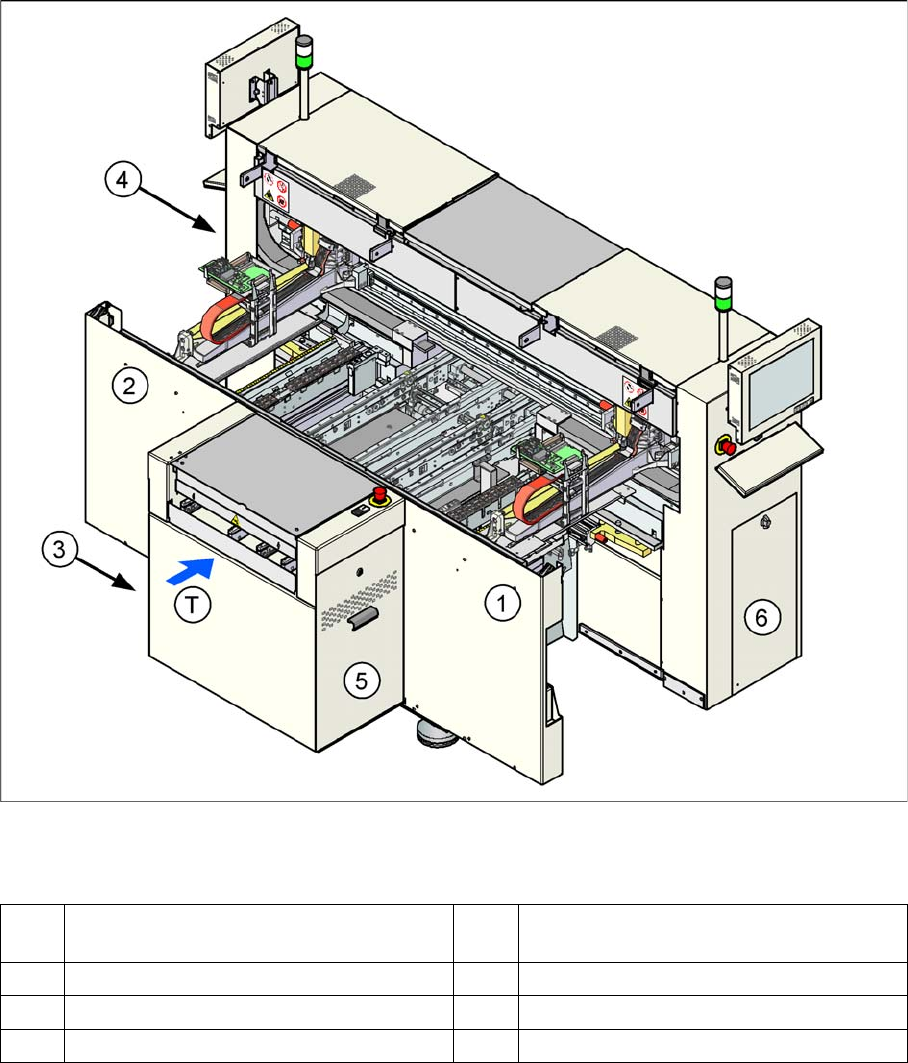
1 Subdistributor (TSP201, ...) (under the cov-
er)
4 Power supply unit
2 Main distributor (under the cover) 5 Axis unit
3 Computer unit 6 Pneumatic unit
T Transport direction
Overview
Electrical System 3.2.1 Axis Unit
22 Service Manual SIPLACE D1/D1i/D2/D2i
3.2.1
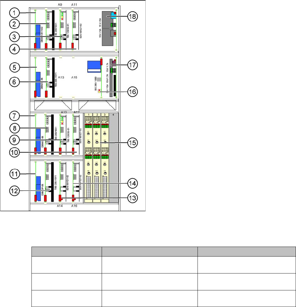
3.2.1 Axis Unit
Axis Unit
Overview of Settings
Axis unit (D2 as example)
Legend
1. X-axis brake board, gantry 1
2. X-axis servo card, gantry 1
3. Star axis servo card, gantry 1
4. Z-axis servo card, gantry 1
5. Y-axis brake board, gantry 1
6. Y-axis servo card, gantry 1
7. X-axis brake board, gantry 2 (for D2 only)
8. X-axis servo card, gantry 2 (for D2 only)
9. Star axis servo card, gantry 2 (for D2 only)
10. Z-axis servo card, gantry 2 (for D2 only)
11. Y-axis brake board, gantry 2 (for D2 only)
12. Y-axis servo card, gantry 2 (for D2 only)
13. DP axis servo card, gantry 1
14. DP axis servo card, gantry 2 (for D2 only)
15. 2 A364 axis cards (D2 has 3 A364 axis cards)
16. Ballast circuit
17. Power supply 5V/15A, 2x15V/5A
18. Power supply 15V/5A
Description Setting Values
Complete axis unit re-
placed
Set the DIP switch for the relevant
location
At placement area 1(OFF/OFF)
Axis card A 364 Install firmware for the relevant axis See "4.1.4 Replacing the A364 Axis
Card" [ ➙ 57].
Servo cards No settings required The servo card for the respective axis
is defined by the hardware.
Overview
3.2.2 Computer Unit Electrical System
Service Manual SIPLACE D1/D1i/D2/D2i 23
3.2.2
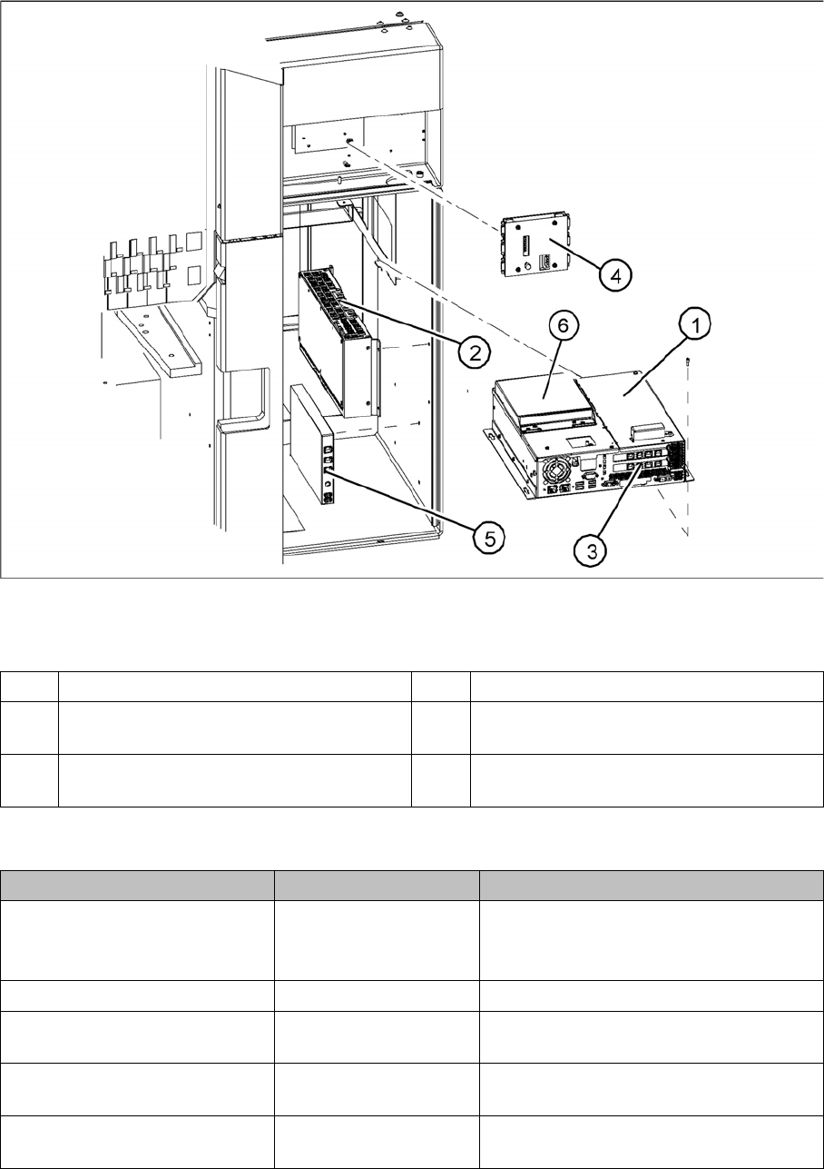
3.2.2 Computer Unit
Computer Unit
Computer unit
Legend
Overview of Settings
1 Station computer [03032341-xx] (Box PC) 4 Video multicoupler [03040316-xx]
2 Machine controller [03047697-xx]
(Micro Box PC)
5 USB hub 2.0 [03032344-xx]
3 Hotlink interface [03032343-xx] 6 Portables USB/DVD/CD drive
[03051205-xx]
Description Setting Comments
Station computer replaced No settings required Backup of machine data
Install software according to respective in-
stallation guide.
Video multiplexer replaced No settings required
Hotlink interface replaced No settings required Make sure that card engages correctly in
the slot.
USB hub 2.0 replaced No settings required Make sure that the USB hub is connected
to the bottom left USB port.
Machine controller replaced No settings required Software installation for machine control-
ler