00195376-05_SM_D1_D1i_D2_D2i_EN.pdf - 第87页
Service Work 4.3.1 Replacing the Complete Drive Unit [00359284] PCB conveyor system Service Manual SIPLACE D1/D1i/D2/D2i 87 Non-modular conveyor, fixed rail 4.3.1 4 . 3 . 1 R e p la c in g t h e C o m p le t e D r iv e U…
Service Work
PCB conveyor system 4.2.16 Hotlink Filter Card [03010670-xx]
86 Service Manual SIPLACE D1/D1i/D2/D2i
2. Non-modular PCB conveyor system with fitting the movable rail for width adjustment
Non-modular conveyor, movable rail
Service Work
4.3.1 Replacing the Complete Drive Unit [00359284] PCB conveyor system
Service Manual SIPLACE D1/D1i/D2/D2i 87
Non-modular conveyor, fixed rail
4.3.1
4.3.1 Replacing the Complete Drive Unit [00359284]
Replacing the Complete Drive Unit [00359284]
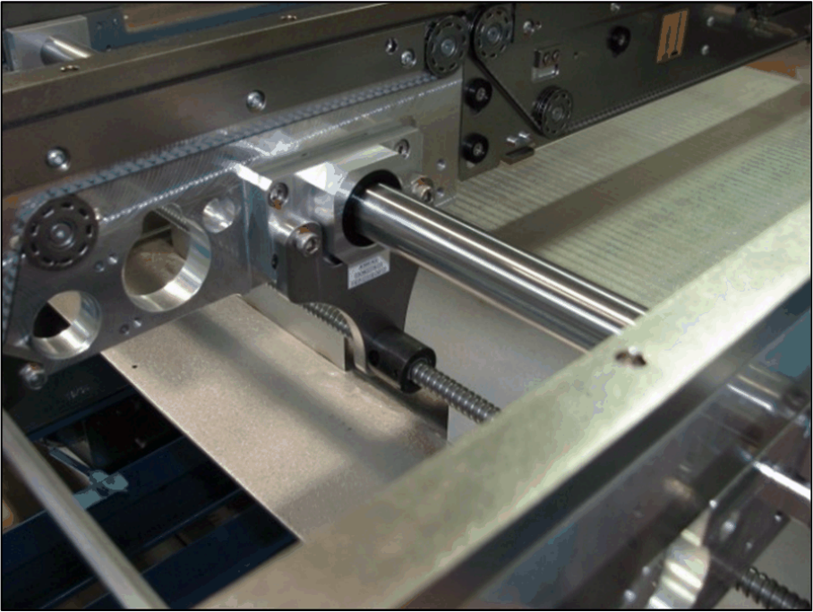
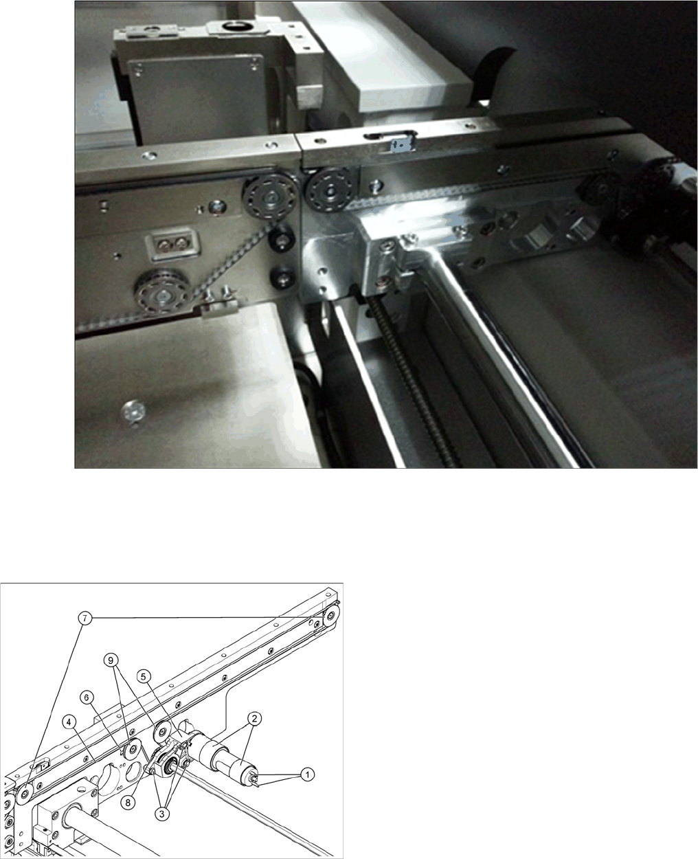
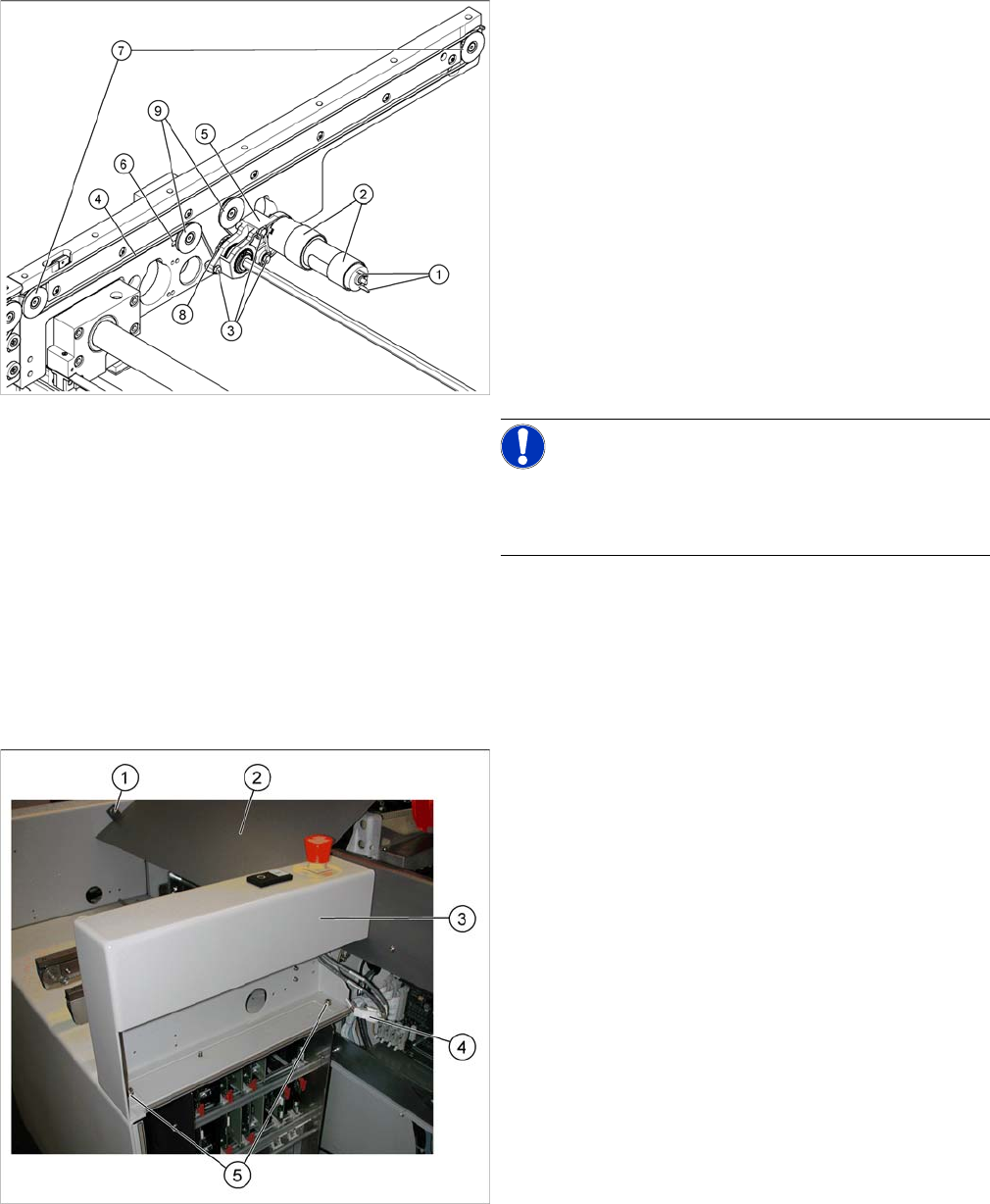
Overview
Example of input conveyor
Legend
1. Cable connections
2. Heat-shrinkable sleeves
3. Fastening screws
4. Conveyor toothed belt
5. Motor mount
6. Slot
7. Toothed disks
8. Belt guide
9. Deflection pulleys
The DC geared motors, including the motor mounts of all
3 conveyor areas, are of like construction. Please bear in
mind the following differences during assembly and dis-
assembly:
▪ The motor mount is installed either horizontally or
vertically, according to the requirements of the instal-
lation site.
Service Work
PCB conveyor system 4.3.1 Replacing the Complete Drive Unit [00359284]
88 Service Manual SIPLACE D1/D1i/D2/D2i
Removal
► Move the side parts of the conveyor system apart, un-
til the motor mount fixture screws (3) are accessible.
This may differ, according to the conveyor type and
area concerned.
► Move the Y gantries into the area outside the PCB
conveyor.
► Switch off the machine and secure it to prevent unau-
thorized reactivation.
► Mark the polarity (brown/white) of the cable connec-
tions (1) - important for the direction of rotation!
► Disconnect the cable shoes from the motor terminals
(1).
► The heat-shrinkable sleeves (2), which hold the con-
necting cable in place, must be stripped off the cir-
cumference of the DC geared motor.
NOTICE!
If necessary, loosen the deflection pulley with slot (6).
See also „Adjusting the Tension of the Conveyor Toothed
Belt“.
► Remove the 3 M4 screws (3) holding the motor mount
in place (5).
► Loosen the clamps holding the hexagonal shaft.
► If necessary, loosen the two screws on the hexagon
shaft guided block of the flexible conveyor side.
When working on the input conveyor, perform the follow-
ing two steps, to access the hexagonal shaft:
► Dismantle the cover (2) by loosening the two screws
(1).
► Dismantle the side part (3) by loosening the two
screws (5).
If necessary, unplug the electrical connections (4)
and place the side part to one side.