00195376-05_SM_D1_D1i_D2_D2i_EN.pdf - 第237页
Settings 6.5.8 Setting the Light Barrier Down Collect&Place Head Service Manual SIPLACE D1/D1i/D2/D2i 237 6.5.8 6 . 5 . 8 S e t t in g t h e L ig h t B a r r ie r D o w n Setting the Light Barrier Down Z end stopper …
Settings
Collect&Place Head 6.5.7 Adjusting the Stop for the Z Axis
236 Service Manual SIPLACE D1/D1i/D2/D2i
6.5.7.3
6.5.7.3 Settings
Settings
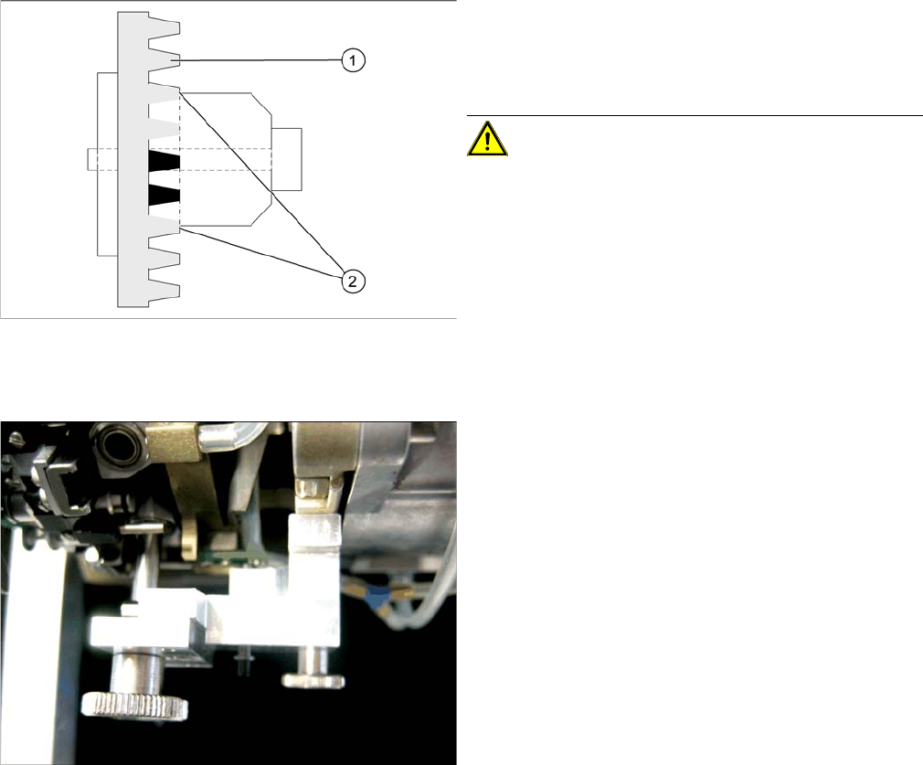
Clamping device Z axis
Legend
1. Belt tension Z Axis
2. Tension jack is positioned on the teeth at the top and
bottom
CAUTION! Make sure that both ends of the ten-
sion jack lie on the teeth of the toothed belt.
Z end stopper star gauge mounted
► Switch off the machine. This setting can be per-
formed directly at the machine.
► The star gauge for setting the Z end stopper is mount-
ed on the C&P head in exactly the same way as the
zero point gauge for the star.
► Remove segment 1 and rotate the star until the
gauge pin fits into the segment guidance.
The star gauge ensures that the star is in the correct po-
sition and that the Z axis is pressed upwards.
► For better access to the Z axis end stopper, unscrew
the cable clamp at one side and turn it to the side.
Then carefully push the flat ribbon cable to the side.
► Check whether the 5/100 mm feeler gauge passes
easily (without resistance) between the Z axis end
stopper and the tension jack (see Fig.).
► If this is not the case, you will need to adjust the Z axis
end stopper setting!
Settings
6.5.8 Setting the Light Barrier Down Collect&Place Head
Service Manual SIPLACE D1/D1i/D2/D2i 237
6.5.8
6.5.8 Setting the Light Barrier Down
Setting the Light Barrier Down
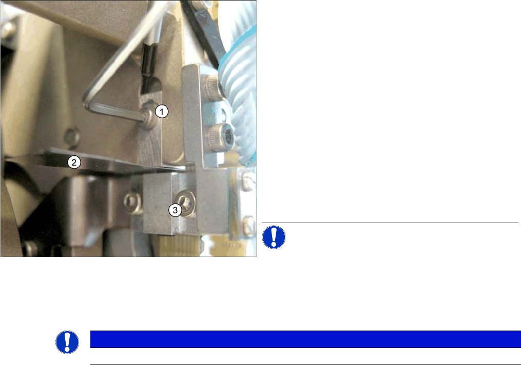
Z end stopper check and adjust
Legend
1. Z end stopper
2. Feeler gauge
3. Clamping device
► Loosen the Z axis end stopper screw.
► Clamp a 15/100 mm feeler gauge between the Z end
stopper and the clamp. Gently press the Z axis end
stopper downwards with the screwdriver and screw
tight.
► It should now be more difficult to extract the 15/
100 mm feeler gauge.
► Check again whether the 5/100 mm feeler gauge
passes easily (without resistance) between the Z axis
end position stop and the tension jack. If this is not the
case, you will need to readjust the setting!
NOTICE! When removing the gauge, make sure
that the gauge pin is extracted first and that then the star
gauge is removed. If you do not observe this order, the
gauge could catch in the segments and damage these!
NOTICE
The light barrier is set with a test probe to a distance of 1.0 mm to the sleeve.
Settings
Collect&Place Head 6.5.9 Determining the Zero Point Correction for the Star Axis of the C&P Head
238 Service Manual SIPLACE D1/D1i/D2/D2i
6.5.9
6.5.9 Determining the Zero Point Correction for the Star Axis of the C&P Head
Determining the Zero Point Correction for the Star Axis of the C&P Head
6.5.10
6.5.10 Adjustment of air pressure values
Adjustment of air pressure values
6.5.10.1
6.5.10.1 Tools and Equipment
Tools and Equipment
▪ A set of slotted screw drivers
▪ Compressed air testing device
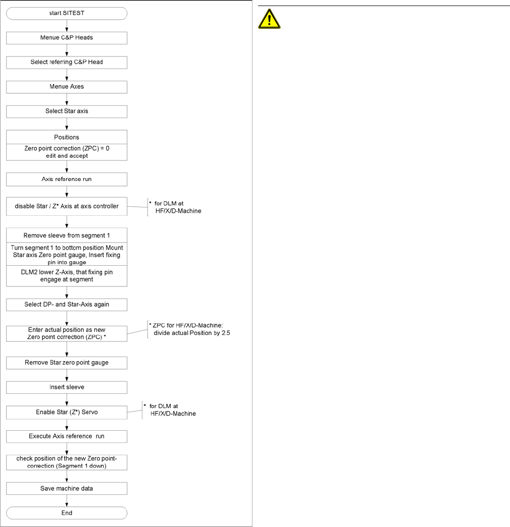
Flow chart zero point correction
CAUTION! When performing this task, follow all
instructions exactly!