00195376-05_SM_D1_D1i_D2_D2i_EN.pdf - 第38页
Overview DLM3 Collect&Place Head 3 .5.6 Overview of Settings 38 Service Manual SIPLACE D1/D1i/D2/D2i 3.5.6 3 . 5 . 6 O v e r v ie w o f S e t t in g s Overview of Settings Description Tools and equipment Values Assem…
Overview
3.5.4 Intermediate Distributor DLM3 Collect&Place Head
Service Manual SIPLACE D1/D1i/D2/D2i 37
3.5.4
3.5.4 Intermediate Distributor
Intermediate Distributor
Overview
3.5.5
3.5.5 Component Cameras
Component Cameras
3.5.5.1
3.5.5.1 Component Camera Type 28 – 18 x 18 – [03014449-xx]
Component Camera Type 28 – 18 x 18 – [03014449-xx]
3.5.5.2
3.5.5.2 Component Camera Type 29 – 27 x 27 – [03018637-xx]
Component Camera Type 29 – 27 x 27 – [03018637-xx]
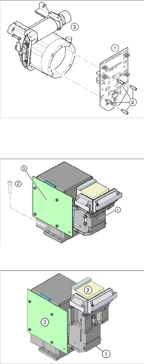
Legend
1. Intermediate distributor
2. 4 M3x10 spacer bolts with snap fasteners
3. Front section of C&P head
Legend
1. Component camera - type 28
2. Fastening screws
3. Illumination control board
Component spectrum: up to 18.7 x 18.7
Field of vision: up to 24.5 x 24.5
Legend
1. Component camera lens system and illumination
2. Camera amplifier
3. Illumination controller
Component spectrum: up to 27 x 27
Field of vision: 31 x 31

Overview
DLM3 Collect&Place Head 3.5.6 Overview of Settings
38 Service Manual SIPLACE D1/D1i/D2/D2i
3.5.6
3.5.6 Overview of Settings
Overview of Settings
Description Tools and equipment Values
Assembly of star on
star motor shaft.
Adjustment with pow-
er pack and zero point
gauge for star.
Finally, check the magnetic neutral position. The dis-
connected drive should not move if the segment pin
for the zero point gauge is removed straight.
Determine zero point
correction factor of star.
Zero point correction
gauge
Enter result of zero point correction with SITEST at
"Positions".
Star encoder resolu-
tion.
None Switch set to 25
DP axis Incremental
encoder setting - dis-
tance to segment disk.
Test probes 1.4 mm –
1.6 mm
Distance 1.5 mm.
Valve positioning drive
settings.
Feeler gauge 0.2 mm; 0.2 mm distance from plunger to valve housing.
Light barrier Z axis
down.
Test probe 1.0 mm Distance 1.0 mm.
Z-terminal block belt,
tension jack
Tension jack must lie on the belt teeth at the top and
bottom.
Z axis belt tension. Belt tension measur-
ing device
Belt tension 280 Hz (+/- 10 Hz).
Z top stop Gauge for Z end stop-
per
Star gauge
Correct position for automatic zero point identification.
Z jaws and circular arc
guide
Feeler gauge 0.02
mm;
0.02 mm gap after complete replacement or new in-
stallation of Z-axis
Air blast tube on star. Sight check Check distance between incremental encoder and air
blast tube.
Air blast supply setting. Feeler gauge Air blast tube must extend approx. 0.7 mm above the
circular arc guide.
Air blast - placement
setting
Compressed air test-
ing device
150 mbar at the pickup and place position, 250 mbar
at the reject position, in each case at an open
9x4 nozzle.
Overview
3.5.6 Overview of Settings Pick&Place Head
Service Manual SIPLACE D1/D1i/D2/D2i 39
3.6
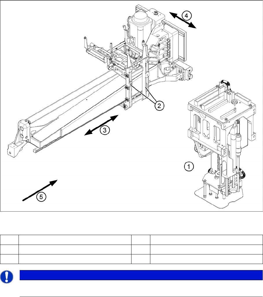
3.6 Pick&Place Head
Pick&Place Head
Legend
1 Pick&Place head (P&P head) 4 Y axis
2 Head mount 5 Transport direction
3X axis
NOTICE
The Pick&Place head (P&P head) is the same as one segment of a Twin Head, at a D3 or X-
series machine.