00195376-05_SM_D1_D1i_D2_D2i_EN.pdf - 第268页
Settings Modular PCB Conveyor System 6.7.5 Width Adjustment Unit 268 Service Manual SIPLACE D1/D1i/D2/D2i ► Perform Calibrate Conveyor in SITEST. 6.7.5.2 6 . 7 . 5 . 2 S e t t in g t h e P n e u m a t ic C y lin d e r P …
Settings
6.7.5 Width Adjustment Unit Modular PCB Conveyor System
Service Manual SIPLACE D1/D1i/D2/D2i 267
6.7.4.1
6.7.4.1 Adjusting the Limit Switch for Initializing the Adjustment Unit
Adjusting the Limit Switch for Initializing the Adjustment Unit
6.7.5
6.7.5 Width Adjustment Unit
Width Adjustment Unit
6.7.5.1
6.7.5.1 Setting the Proximity Switch on the Adjustment Unit
Setting the Proximity Switch on the Adjustment Unit
► When installing the proximity switch (4) , make sure that the proximity switch is level with the adjust-
ment unit housing.
► The switching point is set via the actuator on the conveyor side.
► Move the adjustment unit under the conveyor side, then loosen the actuator using the screw.
► Place the driver onto the 2/10 mm end position scale, press the actuator against the end position
scale and fix with the screw.
► Check the adjustment functions for the relevant adjustment unit and correct the proximity switch po-
sition, where necessary.
► In rare cases, you may need to adjust the actuator.
Limit /initialize switch
NOTICE! This setting is only required after re-
placing the switch or other error functions in the width ad-
justment reference run.
► Move the adjustment unit for the width adjustment by
hand (via the toothed belt) to the conveyor side.
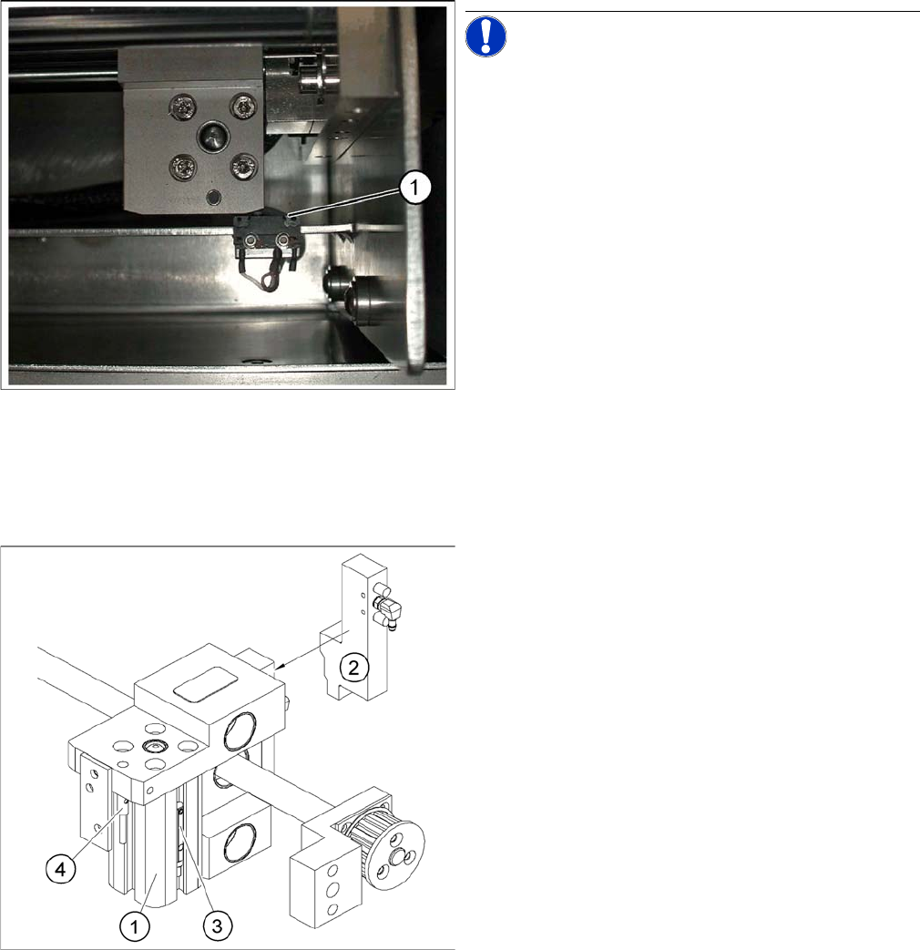
► Loosen the two screws on the limit switch (1).
► Move the limit switch in the slot towards the adjust-
ment unit and make sure that the limit switch is safely
switched on.
► Check the switching state of the corresponding LED
(H11 for TSP 201) (H41 for TSP 301) in the conveyor
control software.
► Fit the limit switch in this position.
► Calibrate the conveyor width via the SITEST pro-
gram.
Overview of the proximity switches on the width adjust
-
ment unit
Legend
1. Short-stroke cylinder
2. Solenoid valve
3. Proximity switch for pneumatic cylinder (for "locking
pin up" recognition)
4. Proximity switch for adjustment unit(for conveyor side
recognition)
▪ The proximity switch (3) serves as a signal for con-
trolling the pneumatic valve of the adjustment unit.
Once the switching point "conveyor side present" has
been reached, the conveyor side is connected via the
pneumatic valve.
Settings
Modular PCB Conveyor System 6.7.5 Width Adjustment Unit
268 Service Manual SIPLACE D1/D1i/D2/D2i
► Perform Calibrate Conveyor in SITEST.
6.7.5.2
6.7.5.2 Setting the Pneumatic Cylinder Proximity Switch on the Adjustment Unit
Setting the Pneumatic Cylinder Proximity Switch on the Adjustment Unit
► Start SITEST
► Set any conveyor width. The adjustment units are positioned directly under the conveyor side.
► Start the I/O menu.
► Activate the pneumatic cylinder.
► Set the proximity switch on the pneumatic cylinder so that the LED (H36/H37 TSP 301) (H64/65
TSP 201) shines when connected.
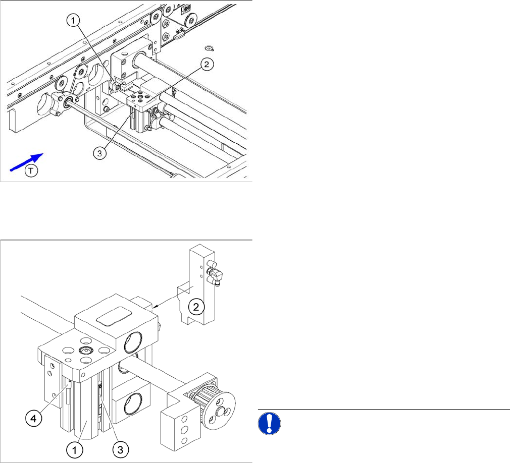
Setting the actuator block for the width adjustment
Legend
1. Fastening screw for the adjustment unit actuator
2. Adjustment unit
3. Proximity switch, adjustment unit
Overview of the proximity switches on the width adjust
-
ment unit
Legend
1. Short-stroke cylinder
2. Solenoid valve
3. Proximity switch for pneumatic cylinder (for "locking
pin up" recognition)
4. Proximity switch for adjustment unit (for conveyor
side recognition)
▪ The proximity switch (3) on the adjustment unit cylin-
der should operate when the adjustment unit pin is
pushed out by the pneumatic cylinder and therefore
connected to the conveyor side. This signal enables
the width adjustment motor.
NOTICE! The proximity switch on the pneumatic
cylinder is set in its engaged state.The proximity switch is
off when the cylinder extended into free space.
Settings
6.7.6 Setting and Checking the Laser Light Barrier for the Stopper Position Modular PCB Conveyor System
Service Manual SIPLACE D1/D1i/D2/D2i 269
6.7.6
6.7.6 Setting and Checking the Laser Light Barrier for the Stopper Position
Setting and Checking the Laser Light Barrier for the Stopper Position
Procedure
► Set the maximum conveyor width. (When using a dual conveyor, position lane 1 so that adjustments
can still be made.)
► In the station software, select General functions --> Cycle mode and switch the Safety mode on.
► Switch over to SITEST.
► Transport a PCB board with a white label on the front edge, through the placement area.
► Activate the relevant laser diode using the input/output functions in SITEST.
DANGER
Laser class 2
The laser light barrier transmitter emits class 2 laser beams. You do not need to take additional
protective measures!
► However, you should never look into the laser beam.
► Only work from the rear of the LASER diode beam (left machine side)! Keep the machine
covers on the right side closed!
NOTICE
The laser beam deflection effect is at its greatest when the conveyor is set to maximum width.
Calibration should therefore always be performed at the maximum conveyor width.
NOTICE
After setting the laser light barrier you must check or re-teach the PCB reference corner!
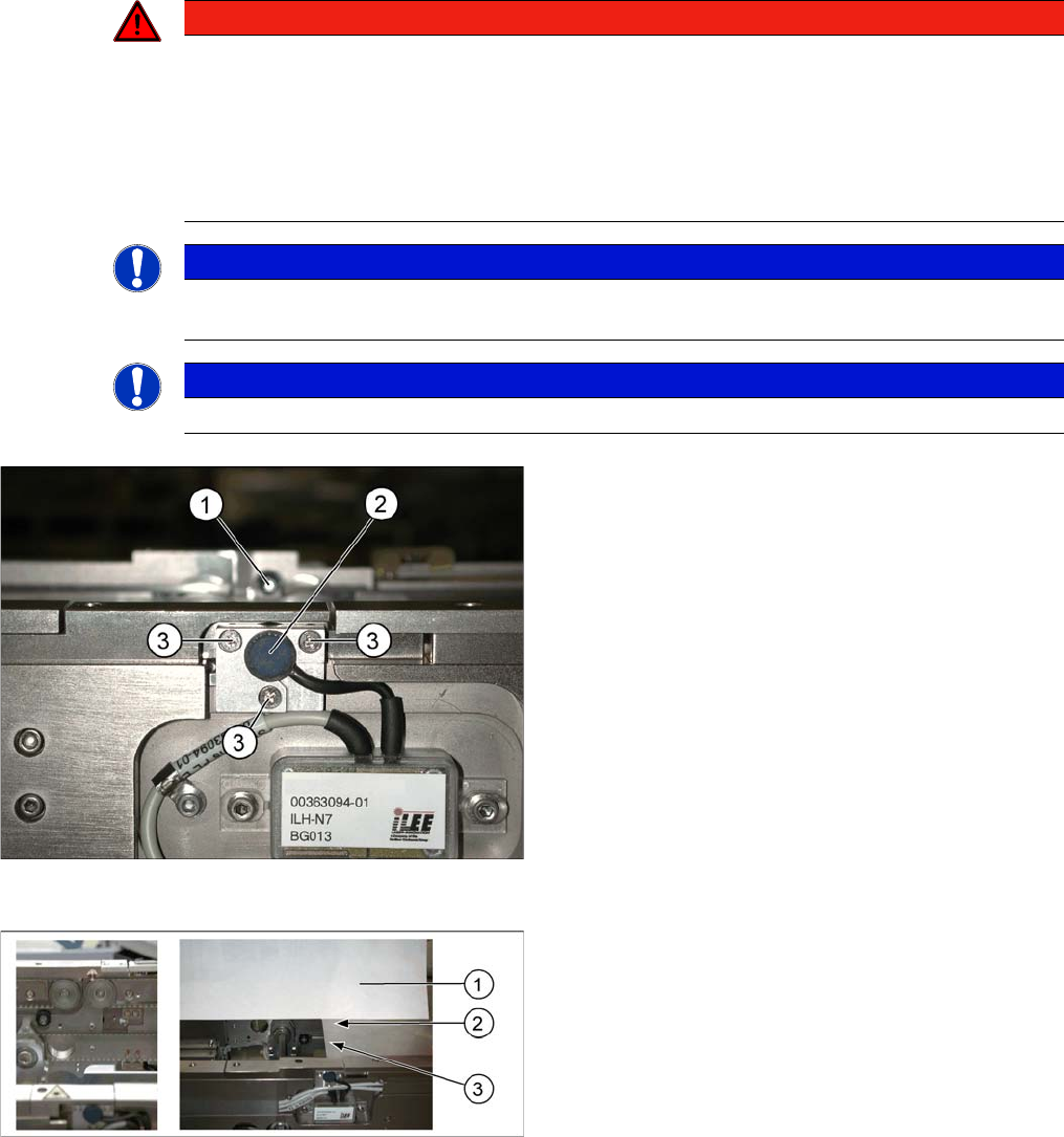
Laser light barrier
Legend
1. Laser receiver
2. Laser diode
3. Setting screws (3x)
Focussing the laser beam
Legend
1. Paper
2. Visible laser beam
3. Board parallel to laser beam