00195376-05_SM_D1_D1i_D2_D2i_EN.pdf - 第207页
Settings 6.2.3 PCB Boards on the Gantry Gantries Service Manual SIPLACE D1/D1i/D2/D2i 207 6.2.3.1 6 . 2 . 3 . 1 G a n t r y H e a d D is t r ib u t o r Gantry Head Distributor Legend See also 6.2.3.1. 1 DIP Switch o …
Settings
Gantries 6.2.3 PCB Boards on the Gantry
206 Service Manual SIPLACE D1/D1i/D2/D2i
6.2.2.5
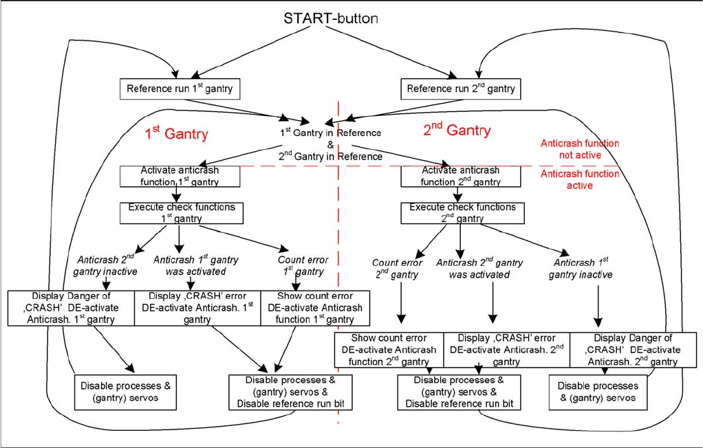
6.2.2.5 Anticrash Function
Anticrash Function
6.2.3
6.2.3 PCB Boards on the Gantry
PCB Boards on the Gantry
The boards on the gantry, as described below, are basically identical and do not depend on the head
configuration of D1, D2 and D4 machines. The CAN bus terminating resistor is fixed onto the gantry head
distributor.
Settings
6.2.3 PCB Boards on the Gantry Gantries
Service Manual SIPLACE D1/D1i/D2/D2i 207
6.2.3.1
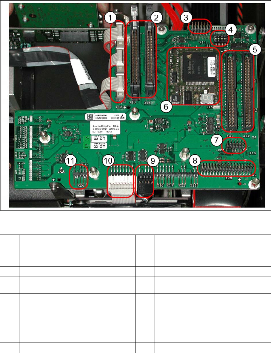
6.2.3.1 Gantry Head Distributor
Gantry Head Distributor
Legend
See also
6.2.3.1.1 DIP Switch on Gantry Head Distributor [ ➙ 208]
6.3.1.2.2 X24 on X-Axis Gantry Head Distributor [ ➙ 215]
1 X20 stepping motor - reject
X19 stepping motor (vacuum/air blast pick-
up
X18 stepping motor - swivel in
7 X24 Test connector for „digital track signals
for X-axis“
2 X13/X14 flat ribbon cable to C&P head 8 X29 connector for Vision board
3 X11 test connector for CAN Bus, SPI Bus,
RS232
9 X12 - DP station (motor, track signals)
4 8 fold DIP switch S1 (see "6.2.3.1.1 DIP
Switch on Gantry Head Distributor"
[ ➙ 208])
10 X10 - connector for vacuum board
5 X30/X31 flat ribbon cable for P&P head for
D1
(D4 not used)
11 X26 - component sensor option
6 TQM module (X5/X6 connector below)
Settings
Gantries 6.2.3 PCB Boards on the Gantry
208 Service Manual SIPLACE D1/D1i/D2/D2i
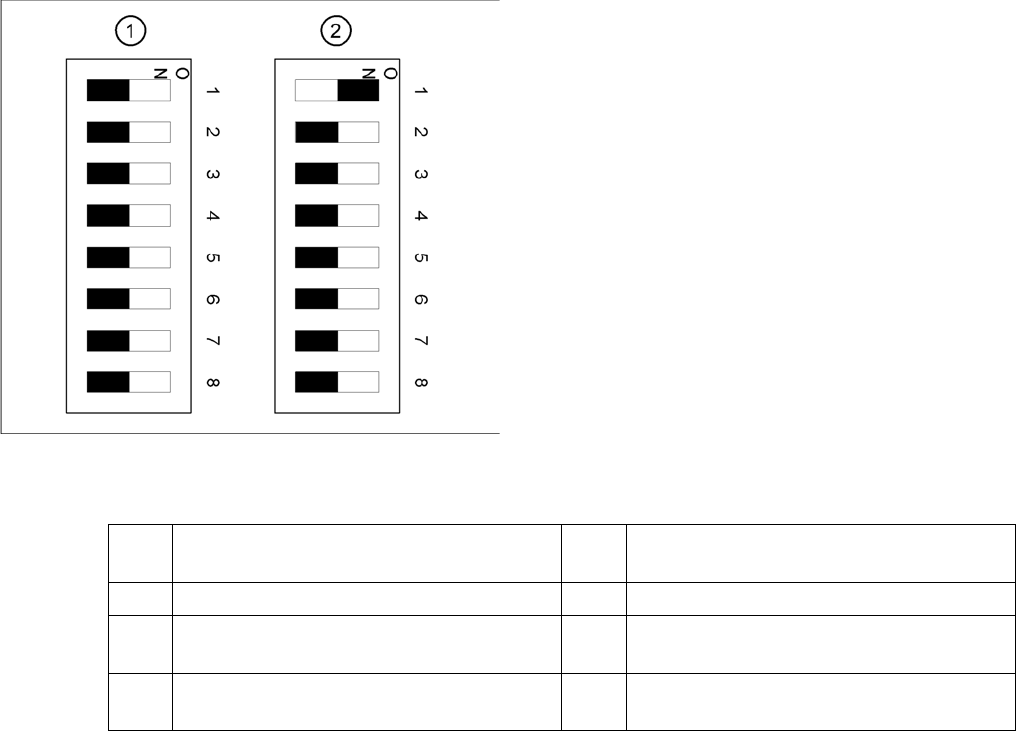
DIP Switch on Gantry Head Distributor
DIP switch
DIP switch 3:
▪ ON: Test mode (without delay)
▪ OFF: Default state (with delay of 3.6 ms+/- 300 us). Z-axis moves downwards, the top LB is released
and the LB down is enabled after a delay of 3.6 ms.
Legend
1. Gantry 1
2. Gantry 2 (for D2 only)
1 P0 – gantry ID0 address switch 1 --> gantry 5 Reset - CAN processor 16 Bit (TQM mod-
ule)
2 P1 – gantry ID1 address switch 2 --> gantry 6 C0 – no current function
3 S1 – switch for DLM head (delay switching
on LB down – Z-axis) (see below)
7 C1 – no current function
4 BL – enable boot loader for serial port 8 S2 – switch for DLM head (no current func-
tion)