00195376-05_SM_D1_D1i_D2_D2i_EN.pdf - 第61页
Service Work 4.1.10 Replacing the Protective Cover Switch [00 335263-XX] Gantries Service Manual SIPLACE D1/D1i/D2/D2i 61 4.1.10 4 . 1 . 1 0 R e p la c in g t h e P r o t e c t iv e C o v e r S w it c h [ 0 0 3 3 5 2 6 3…
Service Work
Electrical System 4.1.8 Replacing the CAN Interface Board [03032346-xx]
60 Service Manual SIPLACE D1/D1i/D2/D2i
4.1.8
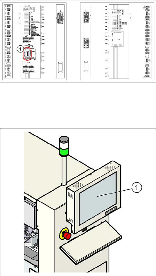
4.1.8 Replacing the CAN Interface Board [03032346-xx]
Replacing the CAN Interface Board [03032346-xx]
Removal/Installation
4.1.9
4.1.9 Replacing the Monitor 1/2 [03040876-xx]
Replacing the Monitor 1/2 [03040876-xx]
Removal/Installation
Legend
1. CAN interface board in main distributor
► Switch off the machine.
► Open the main distributor.
► Unscrew the board and unplug all connections. Label
these for easier reconnection, later.
► Remove the board.
► Insert the new board and reestablish all connections.
► Unplug the connections (24 V voltage supply, video,
USB).
► Unscrew the old monitor (1) and fit the new monitor.
► Calibrate the touchscreen function of the new moni-
tor.
Service Work
4.1.10 Replacing the Protective Cover Switch [00335263-XX] Gantries
Service Manual SIPLACE D1/D1i/D2/D2i 61
4.1.10
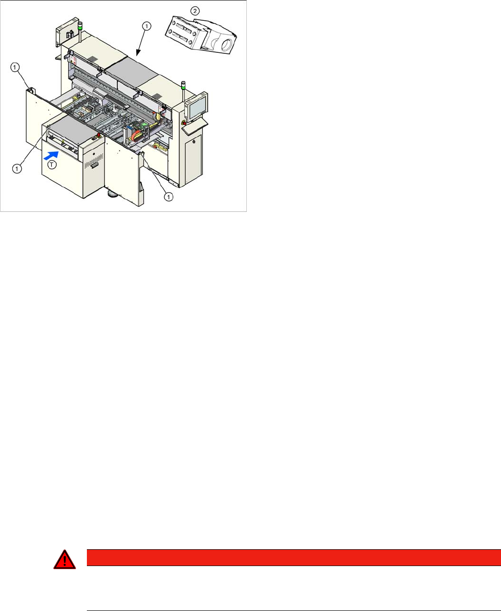
4.1.10 Replacing the Protective Cover Switch [00335263-XX]
Replacing the Protective Cover Switch [00335263-XX]
Removal/Installation
4.2
4.2 Gantries
Gantries
4.2.1
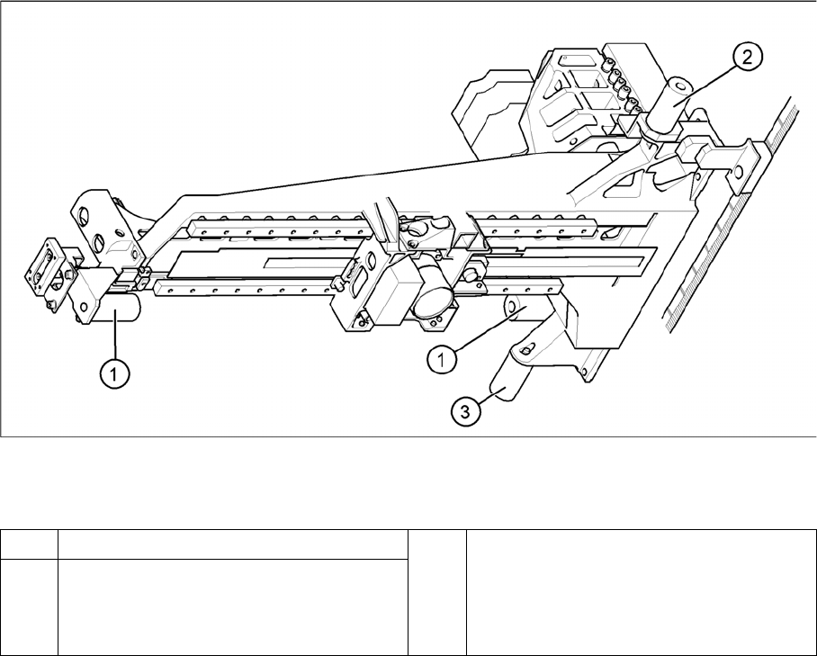
4.2.1 Replacing the Elastomeric Spring [00301040-XX]
Replacing the Elastomeric Spring [00301040-XX]
Tools and equipment
▪ Set of DIN 911 Allen keys
Parts
▪ Elastomeric spring 25 x 10.5 x 50, [00301040-xx]
Removing the elastomeric spring
► Switch the machine off and secure it to prevent unauthorized reactivation as described in section.
Tools and equipment required
▪ Detailed circuit diagrams for SIPLACE D series [Ger-
man: 00194841-xx] [English: 00194842-xx]
Legend
1. Installation position of cover switch at the input/output
side (when cover is open)
2. Cover switch with connection cable, complete
► Where necessary, dismantle the covers.
► Label the appropriate connections at the sector dis-
tributor.
► Unplug the connection cable.
► Unthread the connection cable as far as the cover
switch (1). Where necessary, dismantle the covers.
► Loosen the screws fastening the cover switch.
► Fit the new cover switch.
► Rethread the connection cable and plug in the elec-
trical connections.
► Close the protective cover and check that the cover
switch engages properly and is actuated.
► Correct the position of the cover switch at the slots.
► Switch the machine on and check that the cover
switch activates the safety circuit, when the protective
cover is opened.
► Fit the covers.
DANGER
POWERFUL MAGNETIC FIELD
► Always follow the special safety instructions when working in the vicinity of powerful mag-
netic fields (see section).
Service Work
Gantries 4.2.2 Replacing the Tensioning Keys [00329478-xx]
62 Service Manual SIPLACE D1/D1i/D2/D2i
Elastomeric spring (arrangement in D4 shown)
Legend
► Loosen the M8x20 hexagon socket-head screw in the drilling in the elastomeric spring.
Installing the elastomeric spring
► Use the M8 x 20 hexagon socket-head screw to fix the elastomeric spring.
Settings
None.
4.2.2
4.2.2 Replacing the Tensioning Keys [00329478-xx]
Replacing the Tensioning Keys [00329478-xx]
Tools and equipment
▪ Set of DIN 911 Allen keys
▪ Belt tension measuring device TSM [00326015-xx]
▪ "Measuring belt tensions" operating instructions
Parts
▪ Tensioning keys [00329478-xx]
▪ Tensioning keys [03044521-xx]
1 Elastomeric spring for X-axis 3 All gantries: elastomeric spring for Y-axis
2 Gantries 1 and 3: elastomeric spring for the
Y-axis
Gantries 2 and 4: bracket instead of elasto-
meric spring