S1.pdf - 第44页
0 10 20 30 40 50 60 -40 -20 0 20 40 60 80 100 Droplet position, m m Time, hours Slide 44 Droplet Generator: principle of ope ration • T in is loaded in a vessel & heate d abo ve m elting point • Pressure applied by a…

Droplet generation
Slide 43
Public
0 10 20 30 40 50 60
-40
-20
0
20
40
60
80
100
Droplet position,
m
m
Time, hours
Slide 44
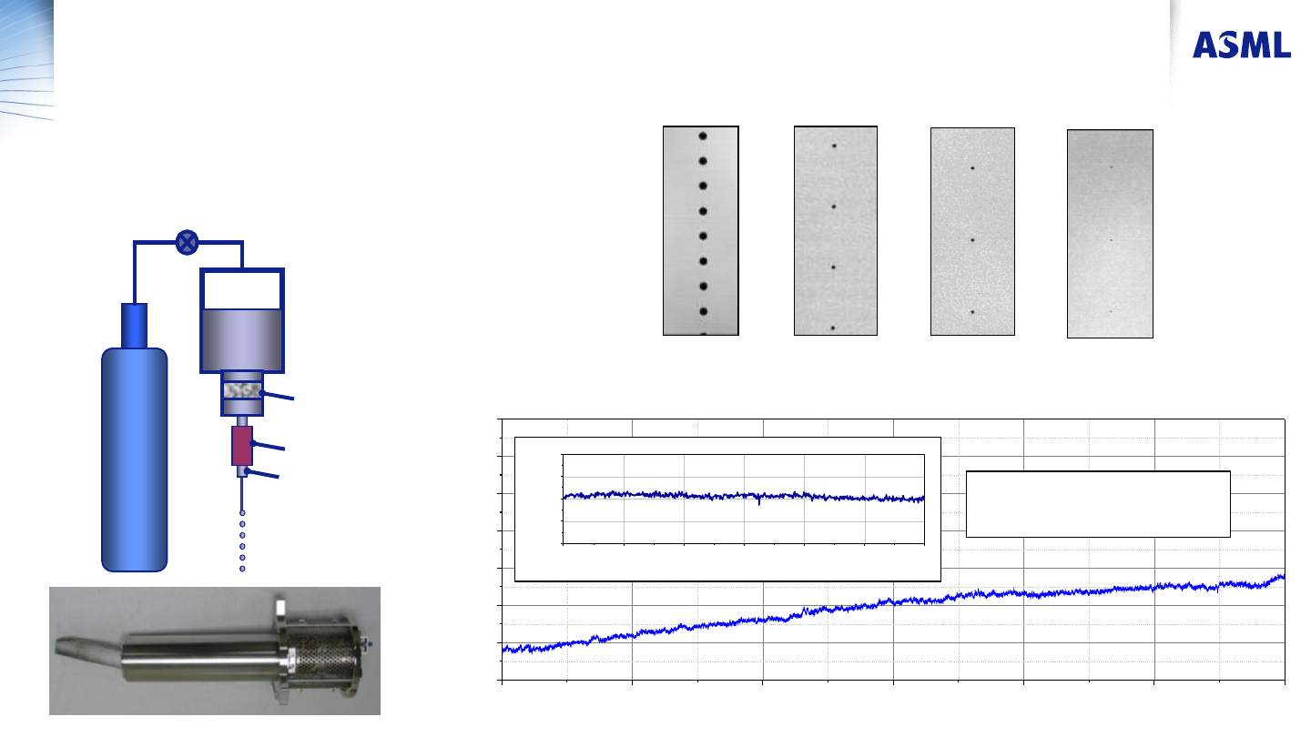
Droplet Generator: principle of operation
• Tin is loaded in a vessel & heated above melting point
• Pressure applied by an inert gas
• Tin flows through a filter prior to the nozzle
• Tin jet is modulated by mechanical vibrations
Nozzle
Filter
Modulator
Gas
Sn
0 5 10 15 20 25 30
-10
-5
0
5
10
Droplet position,
m
m
Time, sec
140 mm 50 mm 30 mm
Short term droplet
position stability σ~1mm
16 mm
Public
Droplet position stability, long and short term
Droplets of different sizes can be generated
Pressure: 1005 psi
Frequency: 30 kHz
Diameter: 37 µm
Distance: 1357 µm
Velocity: 40.7 m/s
Pressure: 1025 psi
Frequency: 50 kHz
Diameter: 31 µm
Distance: 821 µm
Velocity: 41.1 m/s
Pressure: 1025 psi
Frequency: 500 kHz
Diameter: 14 µm
Distance: 82 µm
Velocity: 40.8 m/s
Pressure: 1005 psi
Frequency: 1706 kHz
Diameter: 9 µm
Distance: 24 µm
Velocity: 41.1 m/s
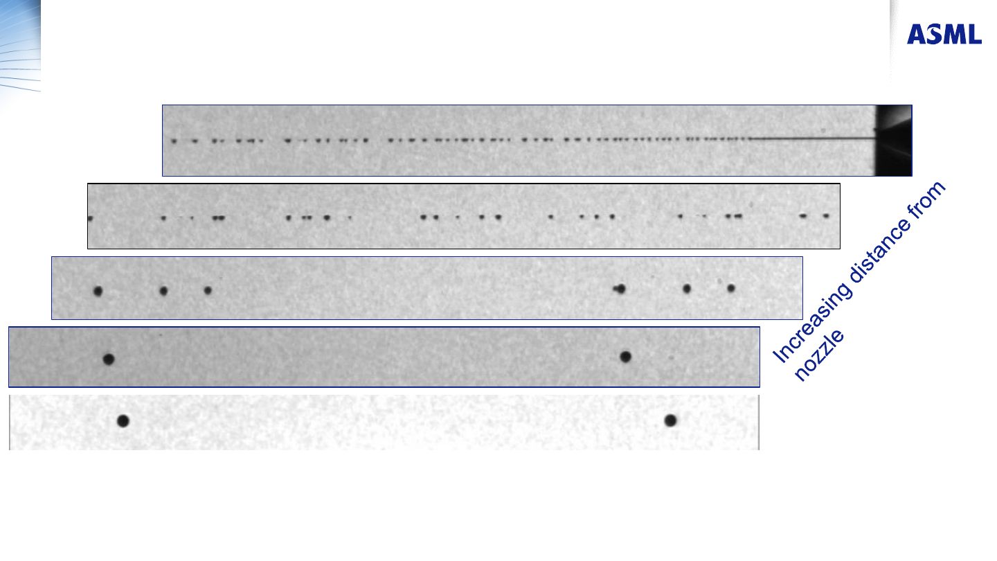
Fig. 1. Images of tin droplets obtained with a 5.5 μm nozzle. The images on the left were obtained in
frequency modulation regime; the image on the right – with a simple sine wave signal. The images
were taken at 300 mm distance from the nozzle.
Slide 45
Droplet Generator: Principle of Operation
Multiple small droplets coalesce together to form larger droplets at larger separation distance
Large separation between the droplets by special modulation
Public