4M184002w_F8S.pdf - 第141页
4OM-1840 1-5-6 1604-001 5.5 Cleaning of high-speed nozzle hole part with pin gauge 5.5 Cleaning of high-speed nozzle hole part with pin gauge ma…
4OM-1840
1-5-5
1604-001
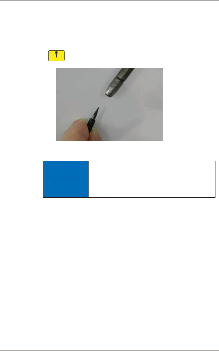
5.4 Method of Blow air
5.4 Method of Blow air
•
Remove dust and dirt etc.
Clean the tapered area of the vacuum nozzle with a lens cleaning cloth.
Notice
Use clean, dry, and non-lubricated air for blow air.
Fig. 4A5-4
NOTICE
Blow air to the head when blow air to the nozzle.
There is a possibility that the clamp jaw breaks when
the air blow is done from the direction of the clamp
jaw to the nozzle.

4OM-1840
1-5-6
1604-001
5.5 Cleaning of high-speed nozzle hole part with pin gauge
5.5 Cleaning of high-speed nozzle hole part with pin gauge
magnifying glass.
•
Select pin gauge
Please select it referring to the combination shown next.
Unit : mm Table 4A5-1
Nozzle ID
Diameter
(center hole
diameter)
Diameter
(minimum hole
diameter)
Pin gauge
size
Part No.
Direction of pin
gauge insertion
Nozzle Tip
Cleaning Jig
HG24C
f
0.1
f
0.08
f
0.08
KYB-M384L-00
0942J1A9
Nail side, Head
side
KYB-M384P-00
0942J1AH
HG33C
f
0.2
f
0.08
f
0.12
KYF-M861K-00
0942J1AC
Nail side, Head
side
KYB-M384R-00
000942J1A5
HG52C
f
0.4
f
0.25
f
0.2
KYF-M861L-00
0942J1AD
Nail side, Head
side
HG82C
f
0.7
f
0.35
f
0.3
KYF-M862U-00
0942J1AE
Head side (a)
HV82C
f
0.7
f
0.35
f
0.3
KYF-M862U-00
0942J1AE
Nail side, Head
side
HG13C
f
0.9
f
0.9
f
0.6
KYB-M384M-00
0942J1AF
Head side (a)
HV13C
f
0.9
f
0.9
f
0.6
KYB-M384M-00
0942J1AF
Nail side, Head
side
HG14C
f
1.1
f
1.1
f
0.8
KYB-M384N-00
0942J1AG
Head side (a)
HV14C
f
1.1
f
1.1
f
0.8
KYB-M384N-00
0942J1AG
Nail side, Head
side
HG15C
f
2.0
f
1.1
f
0.8
KYB-M384N-00
0942J1AG
Head side (a)
HV15C
f
2.0
f
1.1
f
0.8
KYB-M384N-00
0942J1AG
Nail side, Head
side
Note
(a) Pin gauge can not be inserted from nail side.
4OM-1840
1-5-7
1604-001
5.5 Cleaning of high-speed nozzle hole part with pin gauge
•
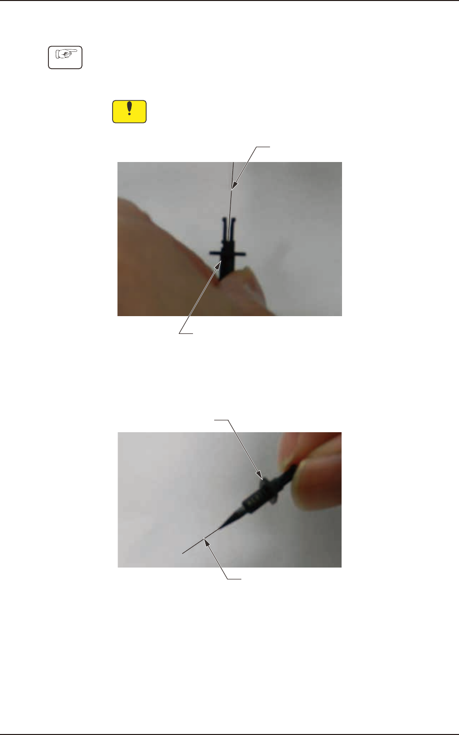
Method of cleaning high-speed nozzle hole
Procedure
(1) Firmly have the high-speed nozzle as shown in the following photograph
and insert it while matching a pin gauge center axis to a center axis of
a high-speed nozzle.
Notice
When a center axis shifts, the head might be damaged.
Pin gauge
High-speed nozzle
Fig. 4A5-5
(2) Put out the pin gauge from the head of the high-speed nozzle.
High-speed nozzle
Pin gauge
Fig. 4A5-6