4M184002w_F8S.pdf - 第145页
4OM-1840 1-5-10 1604-001 5.6 Nozzle Filter Insertion Procedure (3) Insert the nozzle into the nozzle set position. At this time, face the nozzle …
4OM-1840
1-5-9
1604-001
5.6 Nozzle Filter Insertion Procedure
1304-001
5.6 Nozzle Filter Insertion Procedure
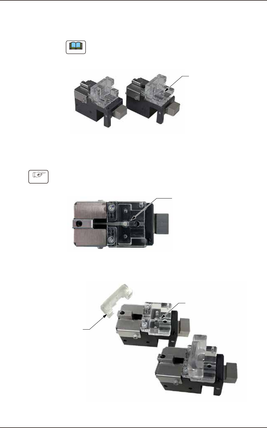
• Filter replacement jig for High-Speed and Middle-Size/Odd-Shape
Note
picking up Middle-Size/Odd-Shape component. The same procedures
apply to both jigs.
For Nozzle picking up
Middle-Size/Odd-Shape
component
For High-Speed Nozzle
Nozzle set position
F4A83
Procedure
tool.
Nozzle filter set position
F4A58A
Acrylic block
(for holing filter)
Acrylic block set on nozzle filter set position
Nozzle filter set position
F4A59A
4OM-1840
1-5-10
1604-001
5.6 Nozzle Filter Insertion Procedure
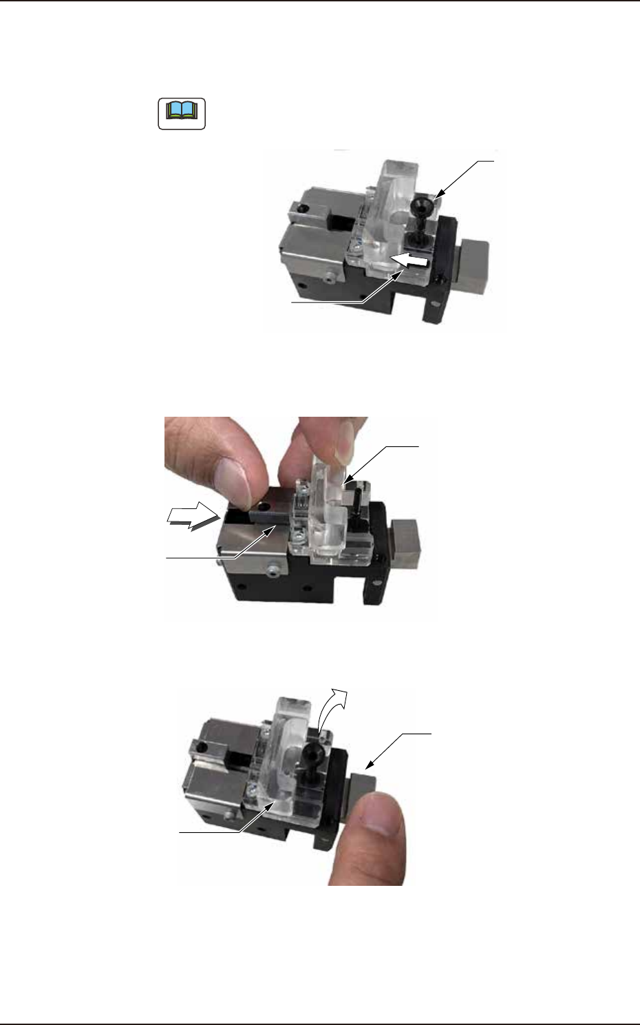
(3) Insert the nozzle into the nozzle set position. At this time, face the nozzle
of white arrow).
Note
Make sure to face the nozzle clearance in the correct direction.
Nozzle clearance for nozzle filter
must face in this direction.
Nozzle
F4A60A
(4) Press the acrylic block and move the slider in the direction of white arrow to
Slider
Acrylic block
F4A62A
(5) Press the lever to detach the nozzle. At this time, a click is heard.
Acrylic block
Press the lever.
F4A82
4OM-1840
1-6-1
1604-001
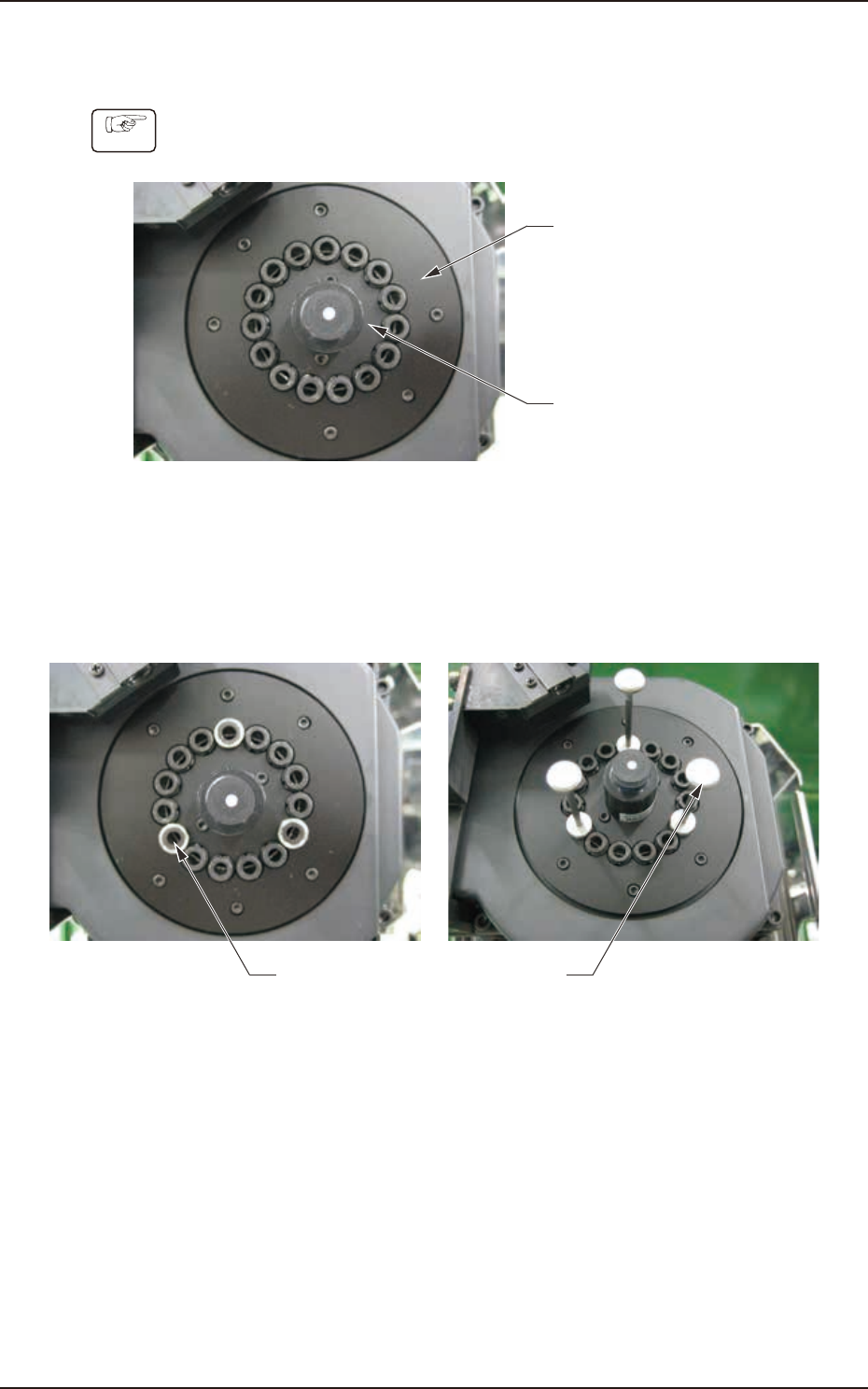
6. Use Procedure of Diusion Plate Setup Jig
6. Use Procedure of Diusion Plate Setup Jig
Procedure
Outer Diffusion Plate
Inner Diffusion Plate
Fig. 4A6-1
(2) Attach the Jigs No. 1 and No. 2 onto the three locations as shown in the
Take care not to damage the linear measure sensor.
Jig 1 Jig 2
Fig. 4A6-2