4M184002w_F8S.pdf - 第73页
4OM-1840 1-2-6 1604-001
4OM-1840
1-2-51604-001
Table 4A2-5
Object Unit
Inspection, Cleaning,
and Lubricating Spots
Work Grease Required Tools Check
4.11 Nozzle Stocker
Section
Nozzle Stocker Sliding
Area
Cleaning,
Lubrication
MP1 Oiled Rag
Shutter Flange Pin
Sliding Section
Cleaning,
Lubrication
NM1
4.12 Control Box
Section
Filter
Cleaning
-----
2.5 Half-Yearly Maintenance
Grease Symbols
MP1
: DAPHNE GREASE MP No. 1
IEL/V
: BARRIERTA IEL/V
Table 4A2-6
Object Unit
Inspection, Cleaning,
and Lubricating Spots
Work Grease Required Tools Check
4.8 X/Y Beam
Section
Cleaning,
Lubrication
IEL/V Oiled Rag, Brush
Places
Inspection
----- -----
Cleaning
----- Rag
Y-Axis Cable Side Face
Cleaning,
Lubrication
IEL/V Oiled Rag, Brush
Y-Axis Cable Fixing
Places
Inspection
----- -----
Y-Axis Liner Scale
Cleaning
----- Rag
4.9 PCB Positionig
Section
Ball Screw Spline
Cleaning,
Lubrication
MP1 Oiled Rag, Hand Grease
Gun, Nozzle (SPK-3C)
Note
The item "Ball Screw Spline (4.9 PCB Positioning Unit)" is for the system
where the Y510mm Single Transfer Unit (Option) has been mounted.
2.6 Yearly Maintenance
Table 4A2-7
Object Unit
Inspection, Cleaning,
and Lubricating Spots
Work Grease Required Tools Check
4.6 Feeder Cart
Section (Cutter)
Fluorine Sheet
Change
----- Screwdriver, Wrench
Urethane Clamp Assy
Change
----- Screwdriver, Wrench
Flat Ring
Change
----- Screwdriver, Wrench, Torque
driver
2.5 Half-Yearly Maintenance

4OM-1840
1-2-61604-001
4OM-1840
1-3-11604-001
3. Maintenance Spots
3. Maintenance Spots
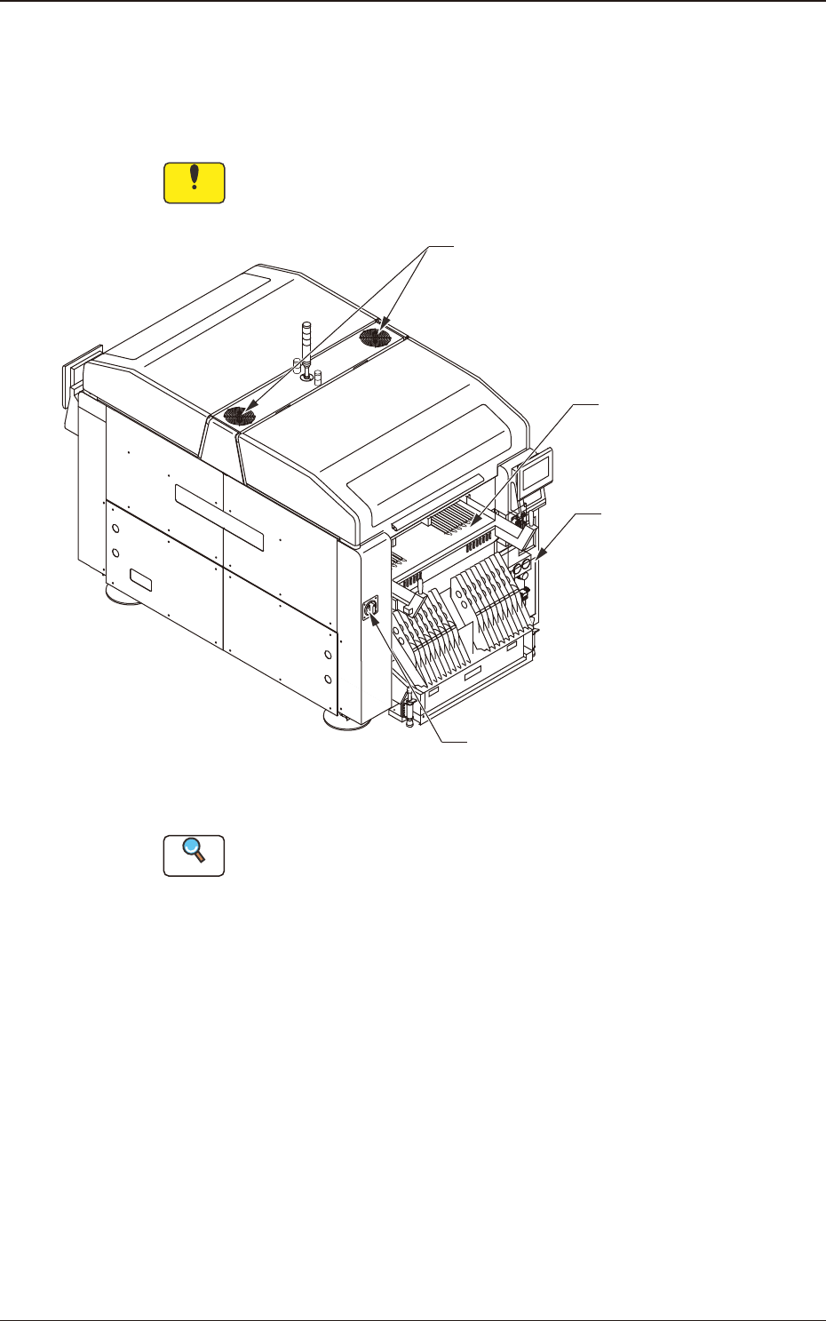
3.1 Whole View
Notice
Any operations with a cover(s) being removed are included.
After the maintenance work, be sure to attach the cover.
Feeder Cart Section
Air Source
Fans Section
Power Breaker
Fig. 4A3-1 Front Side of Machine
Reference
(a) Refer to "4." in "Chapter 1" and the subsequent items for the detailed
information on the spots of each section to be maintained and how to
maintain them.
(b) As for the options, refer to each instruction manual of the specially