00191025-01.pdf - 第12页
0 Introduction SIPLACE 80S /F/G User’s Manual 0.1 General Edition 07/97 from Software Version S R.010.xx 0 - 8

SIPLACE 80S/F/G User’s Manual 0 Introduction
Edition 07/97 from Software Version SR.010.xx 0.1 General
0 - 7
0.1.2 The SIPLACE 80 S Placement Machine
The SIPLACE 80 S placement machine is a modular high-performance placement system with double gantry
axes and two revolver heads on one station. While one placement head is taking components from the feed
modules, the other placement head is mounting the components it had just picked up.
The quality of placement is assured by means of PCB position recognition and component centering via the
vision system as well as by a testing device for checking the identity of the components.
The SIPLACE 80 S is supplied with the necessary data by a line computer running under the UNIX operating
system. It is also possible to connect up with a higher-level data processing system via this line computer.
0.1.3 The SIPLACE 80 F Placement Machine
The SIPLACE 80 F placement machine is a modular high-performance placement system with one revolver
head and one IC head on a single gantry. The revolver head components are mounted first and then the IC
head components.
The quality of placement is assured by PCB position recognition and component centering via the
vision system as well as by means of a testing device for checking the identity of the components.
Optionally a coplanarity laser module can be installed.
Wafflepack changers can be used for the components supply.
0.1.4 The SIPLACE G Gluing Machine
The SIPLACE G operates with three glue cartridges, two of which are used at the same time and which apply
glue simultaneously to the board. To make this possible a special gantry was developed which in addition to
the two basic axes also has an additional axis in the x and in the y directions (kx and kY axes). The SIPLACE
80 F was used as the base module and instead of the two placement heads, one gluing head is used which is
equipped with three gluing units (see Figures 0.4.7 and 0.4.8).
The first gluing unit can be moved in the y direction relative to the basic head with the aid of the additional y
axis.
The second gluing unit can be moved analogously in the x direction with the aid of the additional x axis.
This design makes it possible for the two gluing units to be positioned independently of one another within the
preset limits and thus to operate simultaneously.
The third gluing unit is mounted on the main gantry. It is primarily used for placing particularly large glue spots
with the aid of a large glue nozzle or particularly small glue spots with the aid of a smaller nozzle.

0 Introduction SIPLACE 80S/F/G User’s Manual
0.1 General Edition 07/97 from Software Version SR.010.xx
0 - 8
SIPLACE 80S/F/G User’s Manual 0 Introduction
Edition 07/97 from Software Version SR.010.xx 0.2 Technical Data
0 - 9
0.2 Technical Data
0.2.1 SIPLACE 80S
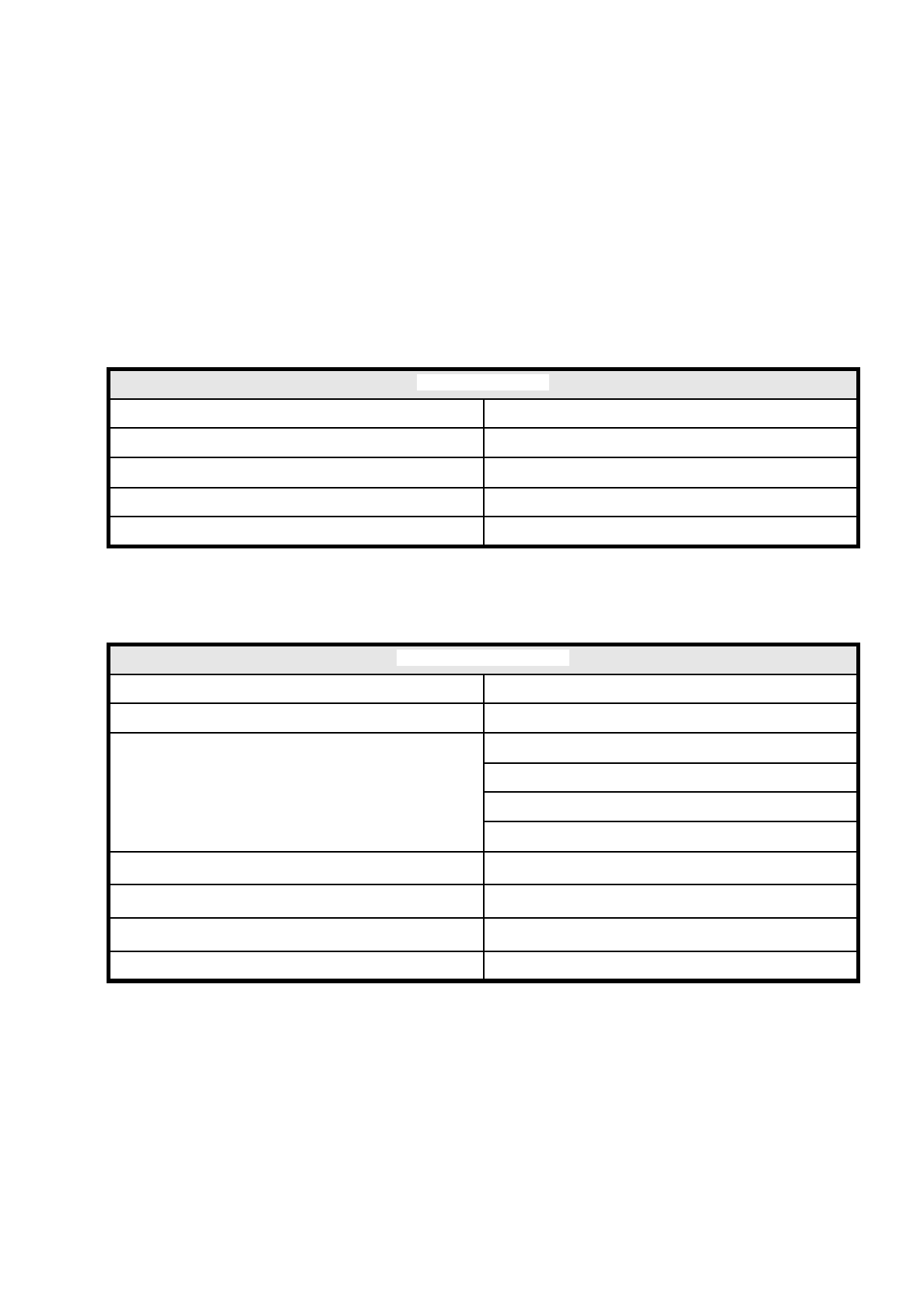
0.2.1.1 Gantry Axes 1 and 2 (80S)
0.2.1.2 Revolver Head 80S (Star Head)
Gantry axes 1 and 2
Drive D.C. servo motors
Path-measuring system Linear incremental scales
Resolution x / y axes 2.5
µ
m
Speed x axis 2.0 m/s
Speed y axis 2.5 m/s
Revolver head (Star head)
Programmable placement force (z axis) 2.4 to 4.0 N
Nozzle types 8
Components to be assembled
Max. height 6.0 mm
Min. pitch 0.5 mm
Dimensions: 0.5 mm x 1.0 mm to 14 mm x 18 mm
Weight up to 2 grams
Path dp1/dp2 turning axes
± 180
o
Resolution dp1/dp2 turning axes
0.1
o
Resolution star head axis
0.005
o
Z axis stroke 14 mm