00191025-01.pdf - 第210页
7 Vision Systems S IPLACE 80S/F/G User’s Manual 7.2 PCB Vision S ystem Edition 07/97 from Software Version SR.010.xx 7 - 18 Line engine er Charac terist ics of t he singl e cross – Informa tion conte nt somewhat lo wer t…

SIPLACE 80S/F/G User’s Manual 7 Vision Systems
Edition 07/97 from Software Version SR.010.xx 7.2 PCB Vision System
Line engineer 7 - 17
●
Using existing structures as fiducials
Instead of fiducials you can also use clearly identifiable structures within the layout. But note here that the
solder resist is accompanied by a drop in contrast.
●
Location of the fiducials
Position the fiducial where there are as few structures as possible and where it will stand out well from its
surroundings. Measuring outwards from the center of the fiducial the clearance should be at least fiducial
size + 1 mm on each side of the fiducial.
●
Types of fiducial
There are 2 types of fiducial:
–
positive fiducials:
The fiducial extends beyond the material of the PCB base.
–
negative fiducials:
The fiducial is etched into the material of the PCB base.
●
Fiducial shape
Always select a well-structured, distinct figure as fiducial shape which is parallel to the axes.
Recommended fiducial shapes:
Rectangle, square or circle
Characteristics
–
Lower information content (fiducials can easily be mistaken for test dots.)
NOTE
Make sure that there are no similar structures in the search area of the fiducials.
–
Less space required in the layout
–
Very robust in comparison to various tin-plating processes (for example hot tinning).
Recommended fiducial dimensions
–
for square and rectangle:
side length 1.2 mm - 2.2 mm
–
for the circle
diameter 1.2 mm - 2.2 mm
Double cross and single cross
Characteristics of the double cross
–
Higher information content
–
Needs more space in the layout
–
Sensitivity with respect to high tinning (bright copper presents more advantages).
–
If too low a fiducial quality is permitted, the risk exists that four incorrect positions will be recognized.
7 Vision Systems SIPLACE 80S/F/G User’s Manual
7.2 PCB Vision System Edition 07/97 from Software Version SR.010.xx
7 - 18 Line engineer
Characteristics of the single cross
–
Information content somewhat lower than with the double cross
–
Needs less space in the layout than the double cross
–
Less sensitive than the double cross where there is high tinning
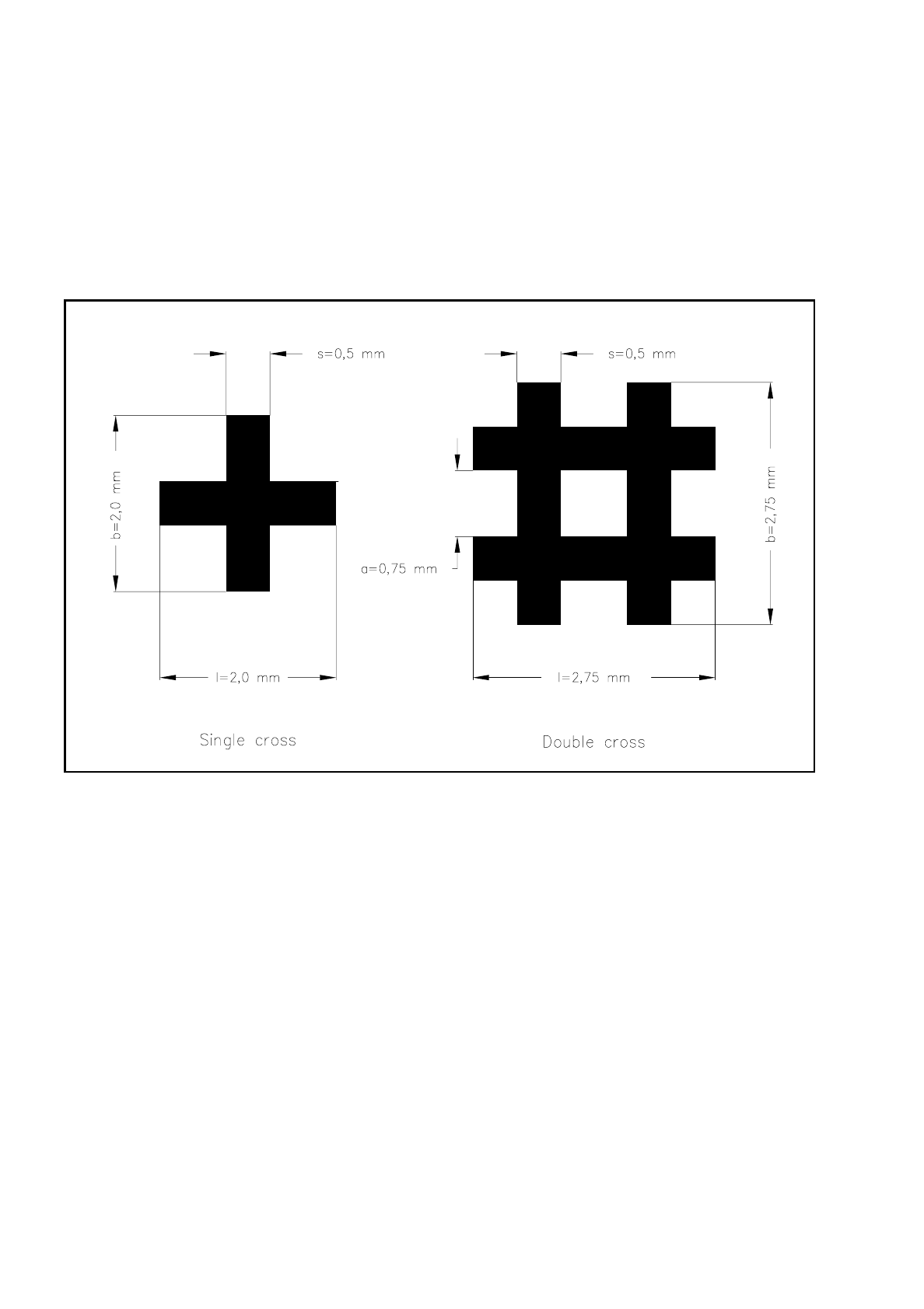
Dimensions of the fiducials:
Single and double cross
Fig. 7.2.3 Single and double crosses with ideal dimensions
The minimum dimensions for a fiducial as regards length (l) and width (b) will depend on the line thickness
(s) and the structure of the fiducial.
–
length (l) and width (b)
For good recognition of a fiducial the length and the width should be at least 0.9 mm with the single
cross and 1.8 mm with the double cross. The ideal dimensions for the single cross are 2.0 mm and for
the double cross 2.75 mm. Under normal circumstances length and width are equal.
–
line thickness (s)
The line thickness can vary according to standard structure widths and will depend on the type of fidu-
cial. Make sure however that the line thickness is always greater than 0.3 mm. The ideal line thickness
for both fiducial types is 0.5 mm.
SIPLACE 80S/F/G User’s Manual 7 Vision Systems
Edition 07/97 from Software Version SR.010.xx 7.2 PCB Vision System
Line engineer 7 - 19
–
Space between lines (a)
The space between the lines also depends on the type of fiducial. It should never be less than 0.5 mm.
With the double cross the ideal spacing should be 0.75 mm.
–
Thickness (d)
Especially with tin fiducials you should make sure that warping does not exceed 1/10 of the width of
the structure. If warping exceeds this it could happen that the fiducial is not evenly illuminated. The
results are different reflection behavior and interference reflections. Recognition of the fiducials is then
no longer guaranteed.
Recommended fiducial dimensions
Evaluation of fiducial shapes
With tinned structures and higher dimensional stability (lower etching fluctuations) full circles or complete
squares can be regarded as very suitable shapes for fiducials (ratio of fiducial thickness to presoldering thick-
ness is high!). If dimensional stability falls, the full circle is to be preferred to the square.
As far as single and double cross fiducial shapes are concerned bright copper is advantageous provided that
oxidation is not yet far advanced.
●
Fiducial surface
Make sure that the fiducial surface is as even as possible and with little oxidation. Avoid wetting the fiducial
with solder resist as this will reduce the contrast with the background or interference reflections may occur.
Similar effects occur with tinned fiducials also.
●
Contrast of the fiducials
To ensure that fiducial recognition is of a high quality select a high brightness contrast between the fiducial
and the base material, i.e. bright fiducials on dark base material or vice versa. For example, apply dark
fiducials on a copper or tin background. In the case of ceramics substrates with a bright surface and unfa-
vorable reflection characteristics it often helps to place dark resistance material underneath, in order to
improve contrast.
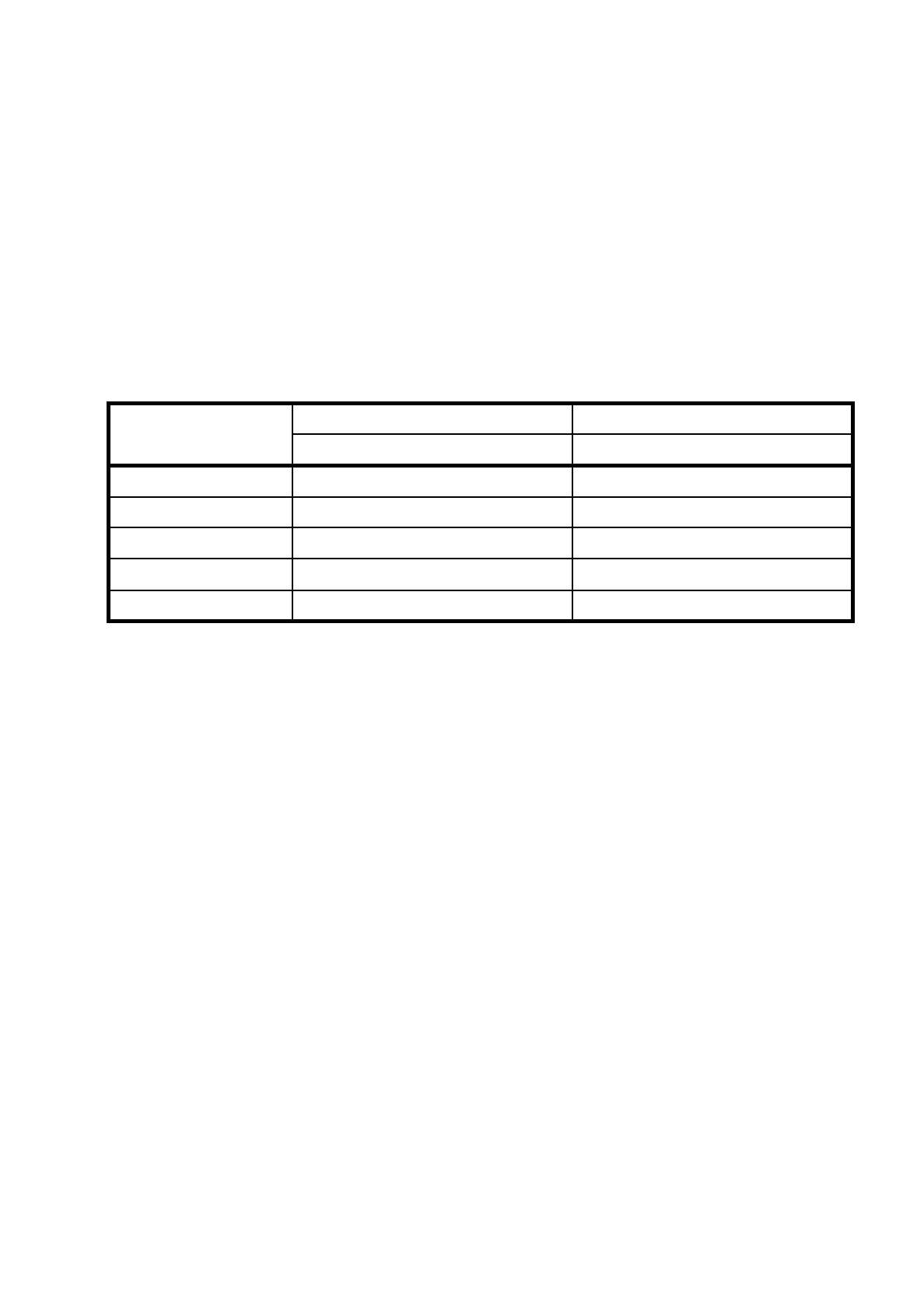
Fiducial type Single cross Double cross
Range Ideal range Range Ideal range
Length (l) 0.9 mm (min) 2.0 mm 1.8 mm 2.75 mm
Width (b) 0.9 mm (min) 2.0 mm 1.8 mm 2.75 mm
Line thickness (s) 0.3 - 1.5 mm 0.5 mm 0.3 - 0.75 mm 0.5 mm
Line spacing (a) — — 0.5 mm (min) 0.75 mm
Thickness (d) < 1/10 of the width of the structure < 1/10 of the width of the structure