00191025-01.pdf - 第390页
SIPLACE 80S/F/G User’s Manual 9 Maintenance Edition 07/97 from S oftware Version SR.010.xx 9.3 Machine Base 9 - 31 9.3. 5.4 Replacing the Filter Cartridge, Cleaning the Filter Bowl NOTE This w ork should on ly be ca rrie…

9 Maintenance SIPLACE 80S/F/G User’s Manual
9.3 Machine Base Edition 07/97 from Software Version SR.010.xx
9 - 30
Hose connector with hose clamp
●
Check the pressure displayed on lefthand manometer (see Fig. 9.3.5): during operation the manometer
should display a pressure of 5.1 bar.
If this is not the case, this may be due to the following reasons:
–
The pressure in the supply network is too low. It must be 6 bar
–
The filter in the compressed air unit is contaminated
–
There is a leak in the compressed air supply or
–
The drain plug has not been tightened up or is leaky.
NOTE
For the compressed air supply use a ½" hose without reducer. The operating pressure of 5.6 bar is preset in
the compressed air unit and cannot be changed.
If it is not possible to achieve the operating pressure of 5.0 bar despite none of the above-mentioned reasons
applying, this means the compressed air unit is defective. You should inform Siemens’ SMD service depart-
ment.
9.3.5.2 2.3 bar Pressure for Stopper
●
Check the pressure displayed on the right-hand, upper manometer (see Fig. 9.3.5, Page 9 - 29): a pres-
sure of 2.3 bar must be displayed.
If this is not the case, remove the cover plate (see Fig. 9.1.1, Page 9 - 3) from the machine base (hexagon
socket spanner, size 3) and correct the setting at the adjustment knob up and to the right.
9.3.5.3 Draining the Condensate
NOTE
This work should only be carried out when there are no components at the star. The condensate will be blown
out under pressure.
●
Remove the cover plate from over the compressed air unit (hexagon socket spanner, size 3).
●
Hold a catch pan under the compressed air unit and unscrew and remove the drain plug (see Fig. 9.3.5,
Page 9 - 29). Finally screw the drain plug back in, making sure it is firmly seated.

SIPLACE 80S/F/G User’s Manual 9 Maintenance
Edition 07/97 from Software Version SR.010.xx 9.3 Machine Base
9 - 31
9.3.5.4 Replacing the Filter Cartridge, Cleaning the Filter Bowl
NOTE
This work should only be carried out when there are no components in the star as the machine needs to be
switched off for this work.
DANGER
∆
!
∆
!
∆
!
Switch the automatic placement system off at the main switch and disconnect from the power supply.
●
Remove the cover over the compressed air unit from the machine base
(see Fig. 9.1.1, Page 9 - 3). To do so, unscrew and remove the two special hexagon socket screws using
a size 3 hexagon socket spanner.
●
In addition turn off the compressed air supply at the stop valve of the compressed air unit (see Fig. 9.3.5,
Page 9 - 29).
●
Open the drain plug for draining the condensate to reduce the pressure in the compressed air hoses (see
Fig. 9.3.5, Page 9 - 29).
●
Remove the filter bowl by rotating it a quarter-turn and pulling it downwards (bayonet closure).
●
Clean the filter bowl if necessary. Only use soapy water for this.
●
Empty the condensate container.
●
Unscrew and remove the support spring and remove the sealing ring.
●
Pull the filter cartridge downwards and out.
●
Slide in the new filter cartridge.
●
Place the seal on the threaded rod and then screw on the support spring. The black plastic disk must be
placed in the filter bowl.
●
Screw the filter bowl back on.
●
Open the stop valve of the compressed air supply (see Fig. 9.3.5, Page 9 - 29).
●
Switch the machine back on at the main switch.
●
Check the pressure at both manometers:
–
operating pressure of the lefthand manometer: 5.6 bar
–
operating pressure for the stopper at the right-hand manometer: stopper: 2.3 bar
NOTE
If, despite changing the filter cartridges, the manometers still do not show 5.0 bar and 2.3 bar this will be
due to other reasons, as described in Section 9.3.5.1 from Page 9 - 28.
●
Fit the cover plate back on the machine base using the size 3 hexagon socket spanner.
9 Maintenance SIPLACE 80S/F/G User’s Manual
9.3 Machine Base Edition 07/97 from Software Version SR.010.xx
9 - 32
9.3.6 Emptying the Rejects Container for the IC Head (SIPLACE 80F)
As regards the position of this rejects container at the machine base, please refer to Fig. 9.3.6.
●
The machine is switched off at the main switch and the sliding safety hoods are open.
●
Check first whether the z axis (sleeve) is in its top end position. If it is not, this indicates a fault. You should
inform Siemens’ SMD service department.
●
Move the gantry away from the rejects container by hand. Do not touch the placement head.
●
Lift the rejects container vertically upwards and off the magnetic disk, making sure that no components
drop into the working area of the machine.
●
Place the empty container back in the center of the magnetic plate.
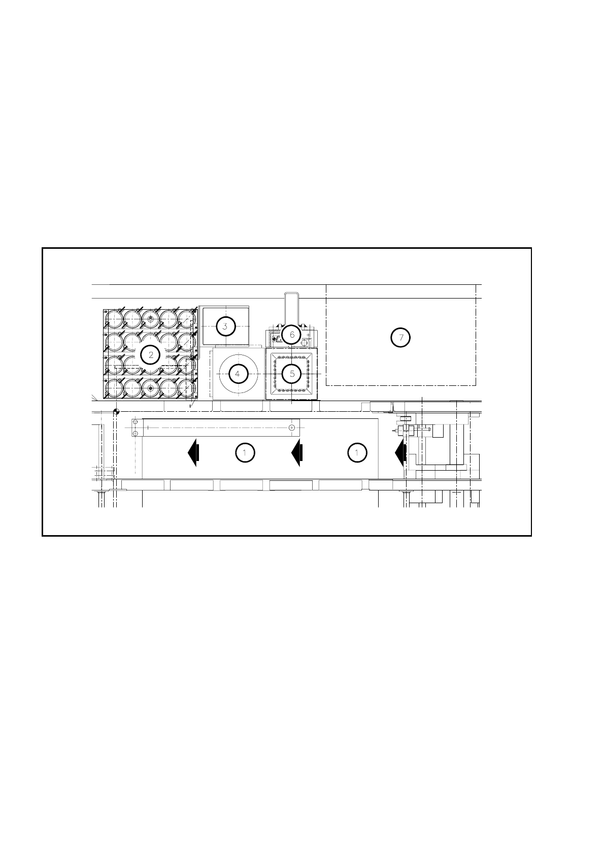
Fig. 9.3.6 Emptying the rejects container for the IC head, position at the machine base
Key to
Fig. 9.3.6
1 Direction of PCB transport
2 IC head nozzle changer
3 Rejects container for IC head
4 Flip-chip sensor
5 IC sensor
6 Coplanarity module
7 Wafflepack changer