00191025-01.pdf - 第432页
SIPLACE 80S/F/G User’s Manual 9 Maintenance Edition 07/97 from S oftware Version SR.010.xx 9.6 IC Head (SIPLA CE 80F) 9 - 73 9.6 IC Head (SIPLACE 80F) 9.6.1 Preparatory Work ● Sel ect: Si ngle f uncti ons → Gantry 1 → IC…
9 Maintenance SIPLACE 80S/F/G User’s Manual
9.5 Revolver Head, Segment Version 2 (New Nozzle Seat) Edition 07/97 from Software Version SR.010.xx
9 - 72
CAUTION
∆
!
The maintenance frequency is directly dependent on the quality of the compressed air used (see above "com-
pressed air maintenance unit")!
If the compressed air specification is not complied with, the silencers should be inspected at correspondingly
shorter intervals.
When removing the silencers pay attention to the wiring. Carefully bend it if necessary to one side before-
hand.
Placement head 1 is in the service position.
DANGER
∆
!
∆
!
∆
!
Switch the automatic placement system off at the main switch and disconnect from the power supply.
●
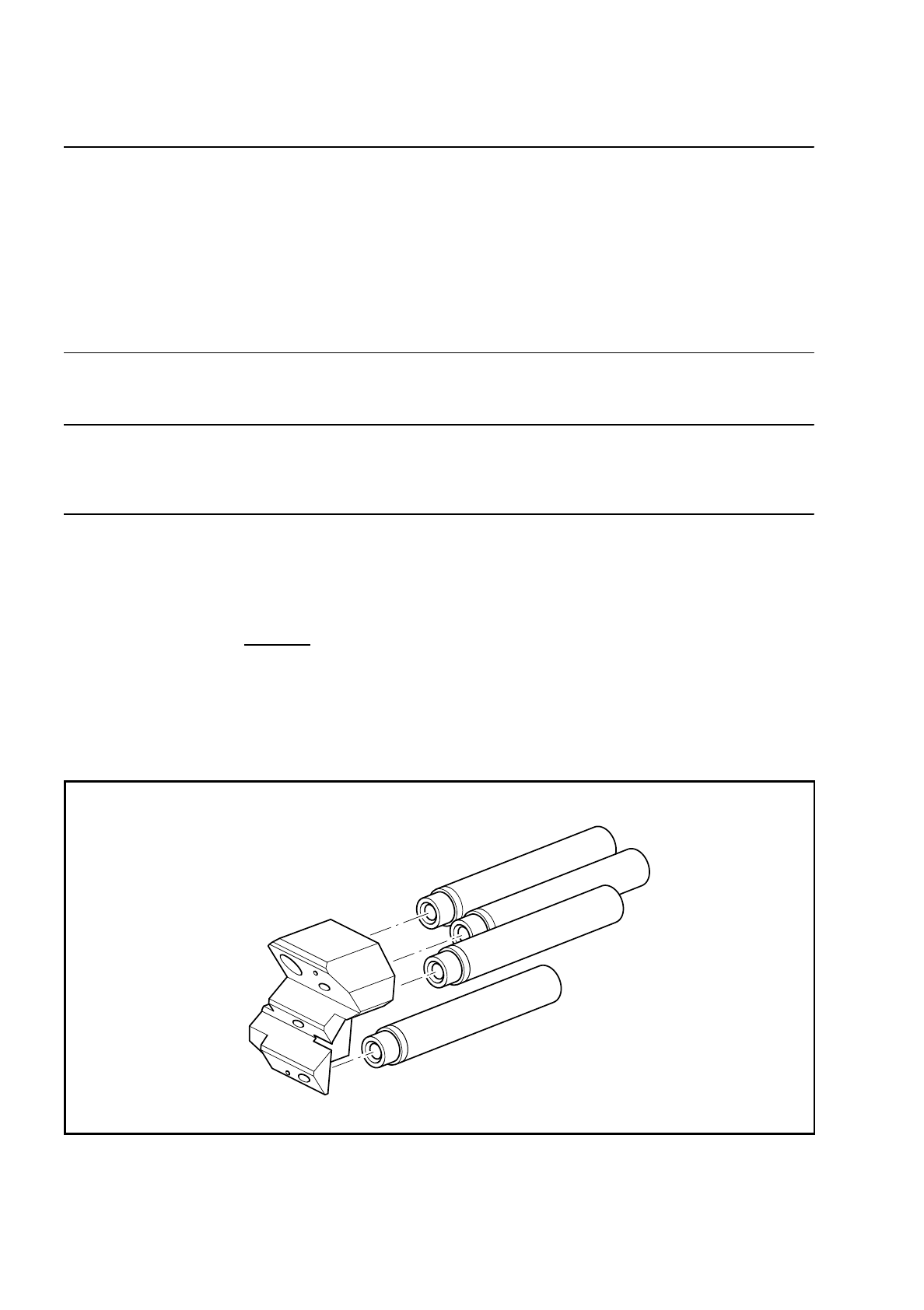
Unscrew and remove - starting at the top - all 4 silencers (see Fig. 9.5.17) in turn from the support plate:
–
Make sure that no parts drop into the machine!
●
Inspect the 4 silencers.
If the silencers are dirty (visible gray - black discoloration), use new silencers.
●
Screw the silencers back into the hole of the support plate in reverse sequence - starting at the bottom -
and as far as the stop.
Attention:
Only use low torque to tighten the silencer since otherwise the silencer
may tear on the thread.
●
Now bring the placement head 2 into the service position: Single functions
→
Gantry 2
→
Go to service
pos'n
→
Start key.
●
Switch off the machine at the main switch and replace the 4 silencers at the placement head 2 (revolver
head, SIPLACE 80 S) analogously to the description for placement head 1.
Fig. 9.5.17 Fitting the silencers
SIPLACE 80S/F/G User’s Manual 9 Maintenance
Edition 07/97 from Software Version SR.010.xx 9.6 IC Head (SIPLACE 80F)
9 - 73
9.6 IC Head (SIPLACE 80F)
9.6.1 Preparatory Work
●
Select: Single functions
→
Gantry 1
→
IC head
→
Return nozzle
DANGER
∆
!
∆
!
∆
!
Switch the automatic placement system off at the main switch and disconnect from the power supply.
●
Open the safety hoods / swivel door.
●
Observe the safety instructions for the coplanarity laser module in Section 9.1
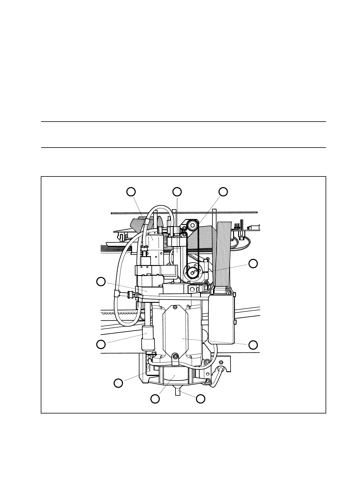
Fig. 9.6.1 Location of the modules requiring maintenance in the IC head
1 Motor/tacho, dr axis 6 Nozzle
2 Venturi nozzle, installed 7 Cover
3 Silencer 8 Motor/tacho, z axis
4 Cover 9 Toothed belt, z axis
5 Encoder flange 10 IC-head sleeve, complete
1 10 9
8
7
65
4
3
2
9 Maintenance SIPLACE 80S/F/G User’s Manual
9.6 IC Head (SIPLACE 80F) Edition 07/97 from Software Version SR.010.xx
9 - 74
●
Check to see whether the z axis is in its top end position and move the IC head by hand to a favorable
working position by pressing on a suitable side of the gantry carriage, thus ensuring that the head does not
get damaged.
Currently when the ’Go to service position’ option in the Gantry functions menu is selected the service
position of the star head will be approached. The IC head service position button will be available at a later
date.
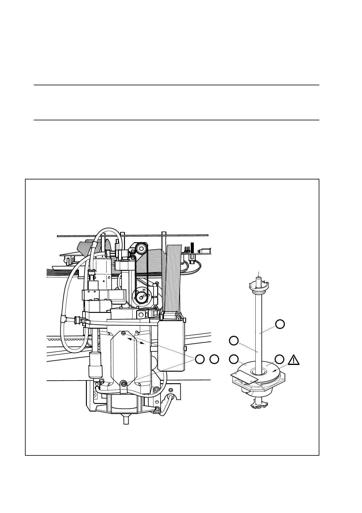
9.6.2 Oiling the Sleeve and Cleaning the Encoder Disk
Carry out maintenance, as shown in Fig. 9.6.2.
Fig. 9.6.2 Oiling the sleeve and cleaning the encoder disk
A D
,
C
B
2
1