00191025-01.pdf - 第416页
SIPLACE 80S/F/G User’s Manual 9 Maintenance Edition 07/97 from S oftware Version SR.010.xx 9.5 Revolver Head, Segment Version 2 (New Nozzle Seat) 9 - 57 Key to Fig. 9.5.9 (Maintenance of the vacuum nozz le including o-ri…
9 Maintenance SIPLACE 80S/F/G User’s Manual
9.5 Revolver Head, Segment Version 2 (New Nozzle Seat) Edition 07/97 from Software Version SR.010.xx
9 - 56
●
Check the stop plates and replace them if damaged: unscrew 2 x M1.6 countersunk screws.
●
Bring the screwdrivers now into their exact rotational positions:
Screwdriver 1: horizontal position. Screwdriver 2: 30 degree position (see marking!)
●
Finally bring the z axis by hand into the top end position.
9.5.8 Vacuum Nozzles
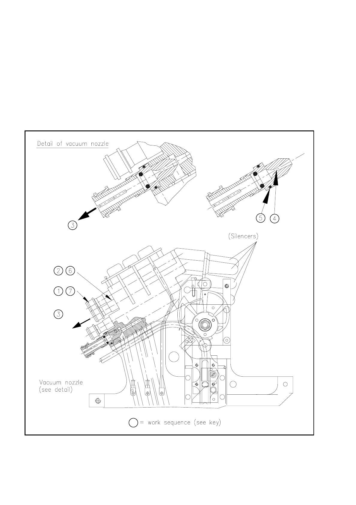
Fig. 9.5.9 Maintenance of the vacuum nozzles (view of direction of fitting of the placement head)

SIPLACE 80S/F/G User’s Manual 9 Maintenance
Edition 07/97 from Software Version SR.010.xx 9.5 Revolver Head, Segment Version 2 (New Nozzle Seat)
9 - 57
Key to
Fig. 9.5.9
(Maintenance of the vacuum nozzle including o-rings) :
1. Undo the quick-release closure of the compressed air connections at the vacuum nozzles:
Slide the red ring towards the nozzle and pull off the hoses.
2. Undo the fastening of the vacuum nozzles (3 x M2 hexagon socket screws).
3. Pull out the vacuum nozzles.
4. Clean the hole of the vacuum nozzles and also the O-rings with alcohol. Grease the O-rings sparingly with
UNISILKON L250L.
5. Check the correct seating of the O-rings and slide the vacuum nozzles into the holes as far as the stop.
6. Fasten the vacuum nozzles at the collar (hexagon socket screws).
7. Reconnect the compressed air hoses (pay attention to the different lengths!) and secure the hoses by slid-
ing the red ring upwards.
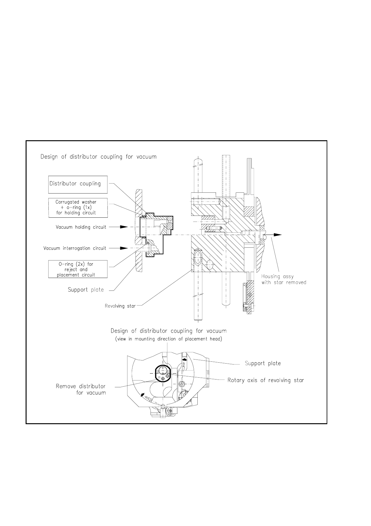
9.5.9 Vacuum Distributor Coupling
The vacuum distributor coupling is plugged into the support plate at the centre of rotation of the star and is
only accessible after the "housing complete with star" has been removed (see Fig. 9.5.10).
For this reason maintenance of the vacuum distributor coupling is always carried out at the same time as
maintenance of the "housing complete with star".
NOTE
If there is marked clogging of the holes of the vacuum distributor coupling you should inform the SMD service
department of Siemens AG.:
In the first place, the causes of the clogging must be determined, such as, for example, the compressed air
specification not being complied with, the compressed air filter not been replaced at the proper time, and so
on.
In the second place, it may be necessary for the entire hole system in the placement head to be given a thor-
ough cleaning back at the factory!
Spare parts
O-ring for placement and reject circuit, 4 x 1.2 NBR 70 B, Item No. 00303110-01 (1 of each)
O-ring for holding circuit, 9 x 1 NBR 70 B, Item No. 00201383-01 (1 piece)
9.5.9.1 Cleaning the Holes and Outer Surface
●
The "housing complete with star" has been removed (see "Removal of the housing complete with star").
●
Pull the vacuum distributor coupling vertically forwards off the support plate (do not tilt!).
●
Have a look to see whether there is severe clogging (see NOTE above).
If the clogging is only slight then as a precaution make a check all the same as to whether the maintenance
of the compressed air unit has been carried out regularly, or whether there is another reason.
9 Maintenance SIPLACE 80S/F/G User’s Manual
9.5 Revolver Head, Segment Version 2 (New Nozzle Seat) Edition 07/97 from Software Version SR.010.xx
9 - 58
●
If clogging is slight proceed as follows:
●
Remove the O-rings from the vacuum distributor coupling, which has been removed, and the bore in
the support plate (see Fig. 9.5.11).
●
With alcohol (no solvent!) clean the visible surfaces of the coupling, and in particular also the bores for
the O-rings and also the external circumference of the connection tube of the holding circuit.
●
Clean the bore in the support plate and the circumference of the two small connection tubes.
●
With clean compressed air blow out thoroughly the individual holes - only the holes of the distributor
coupling, not of the support plate ! - and the outer surface of the distributor coupling. All surfaces of
and holes in the coupling and the support plate must then be dry!
Fig. 9.5.10 Location of the vacuum distributor coupling on the support plate, and removal of the distributor coupling