00191025-01.pdf - 第295页
SIPLACE 80S/F/G User’s Manual 7 Vision Systems Edition 07/97 from S oftware Version SR.010.xx 7.7 Guidelines for Describing P ackage Forms Line engi neer 7 - 103 7.7.5 Parameters for the Measuring Methods Possi ble seque…
7 Vision Systems SIPLACE 80S/F/G User’s Manual
7.7 Guidelines for Describing Package Forms Edition 07/97 from Software Version SR.010.xx
7 - 102 Line engineer
–
If the components are larger than 32 mm x 32 mm, a multiple measurement will be carried out automati-
cally in the vision system.
7.7.4 Test Package Form - Visual Representation / Programming Mea-
surement Types
–
In the ’Test component’ menu, a component is picked up and then moved to the camera and mapped in its
0° position. The component is displayed with respect to its insertion angle at the revolver head of the S-15/
F3.
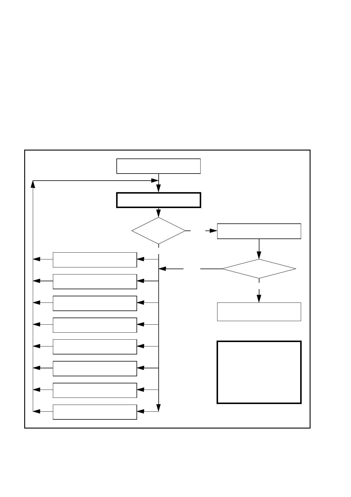
Fig. 7.7.5
Order in which package forms are programmed at the station
Important note:
The manipulation of
components at the station
must remain the exception,
rather than the rule.
In general, only a few components
have to be changed.
Are the results
constant?
No
Measure component
Error
Yes
Repeat the measurement
and view the results
Yes
Assemble component
several times
8. Modify the contrast sensitivity
(Program table)
7. Modify pin/ball
dimensions
6. Modify pin/ball contrast
5. Modify component dimension
4. Modify measuring modes and
measuring
3. Modify lighting
2. Display component
1. Handling error:pick-up angle,
nozzle type, component on nozzle,
No
Measure component
„RETURN“ next measurement
SIPLACE 80S/F/G User’s Manual 7 Vision Systems
Edition 07/97 from Software Version SR.010.xx 7.7 Guidelines for Describing Package Forms
Line engineer 7 - 103
7.7.5 Parameters for the Measuring Methods
Possible sequences of measuring methods
It is also possible to program other sequences, such as corner followed by lead or lead only. Such combina-
tions are very unusual, however. If the component is defined in the package form editor, then the measuring
methods will be pre-assigned. However, in some cases it may be necessary to modify the measuring methods
at the station so that the component can also be optically centered.
The results from the last measurement are always saved. The previous measurement is used as a rough cen-
tering step for the next measurement and thus helps to reduce the measuring window.
The more measuring methods are used, the longer the entire measuring procedure will be. A large number of
measuring methods for a component can delay the head cycle. This applies to the revolver head in SIPLACE
80S-15/F3 automatic placement machines, in particular.
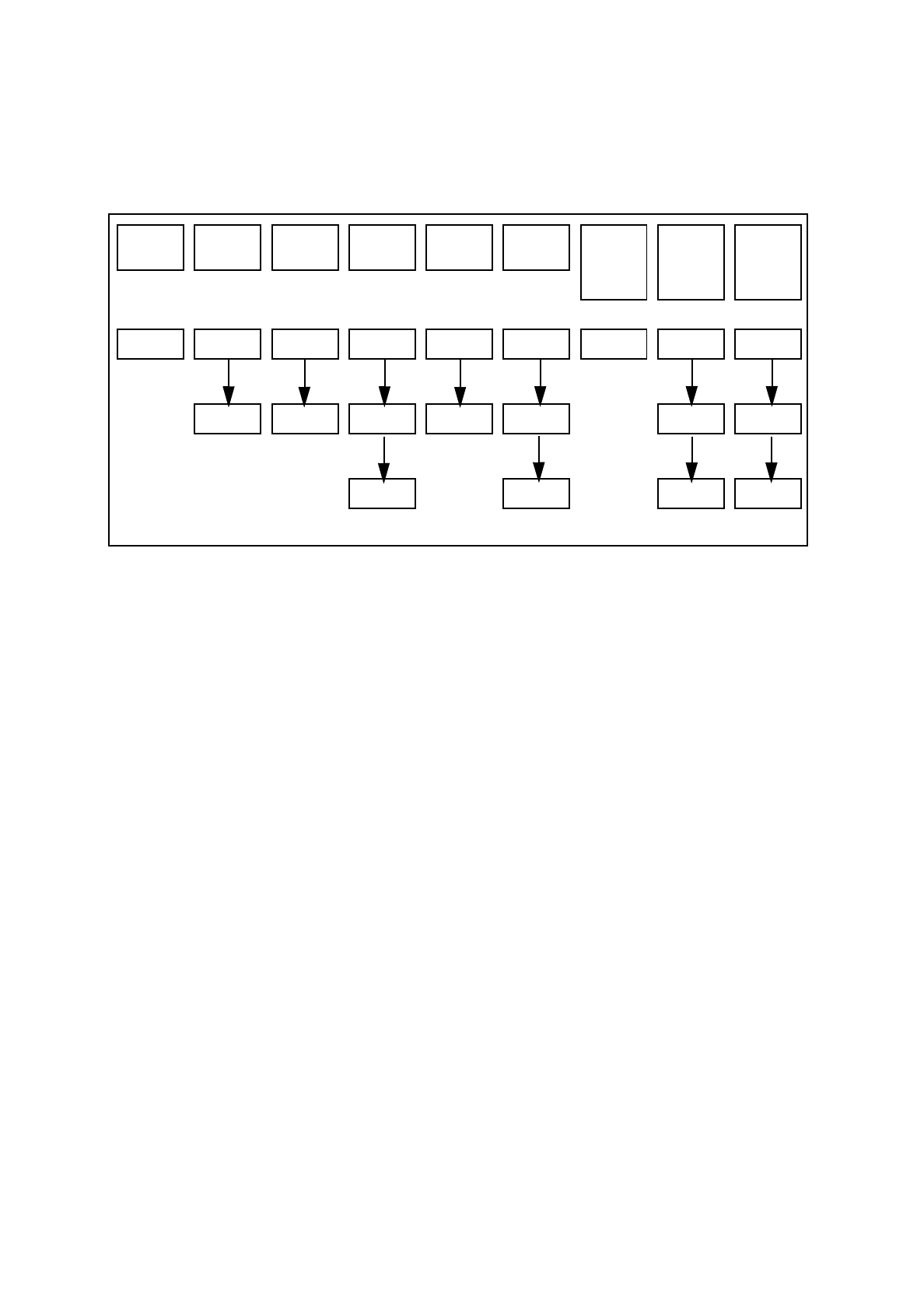
PDC/
FDC
FDC FDC FDC FDC FDC
Flip
chips
S15
Flip
chips
F3
Ball
grid
array
Size Size Size Size Row Row Size Size Size
Lead Corner Corner Corner Corner Grid Grid
Lead Lead Ball Ball
T
ab. 7.7.2 Possible sequences of measuring methods
7 Vision Systems SIPLACE 80S/F/G User’s Manual
7.7 Guidelines for Describing Package Forms Edition 07/97 from Software Version SR.010.xx
7 - 104 Line engineer
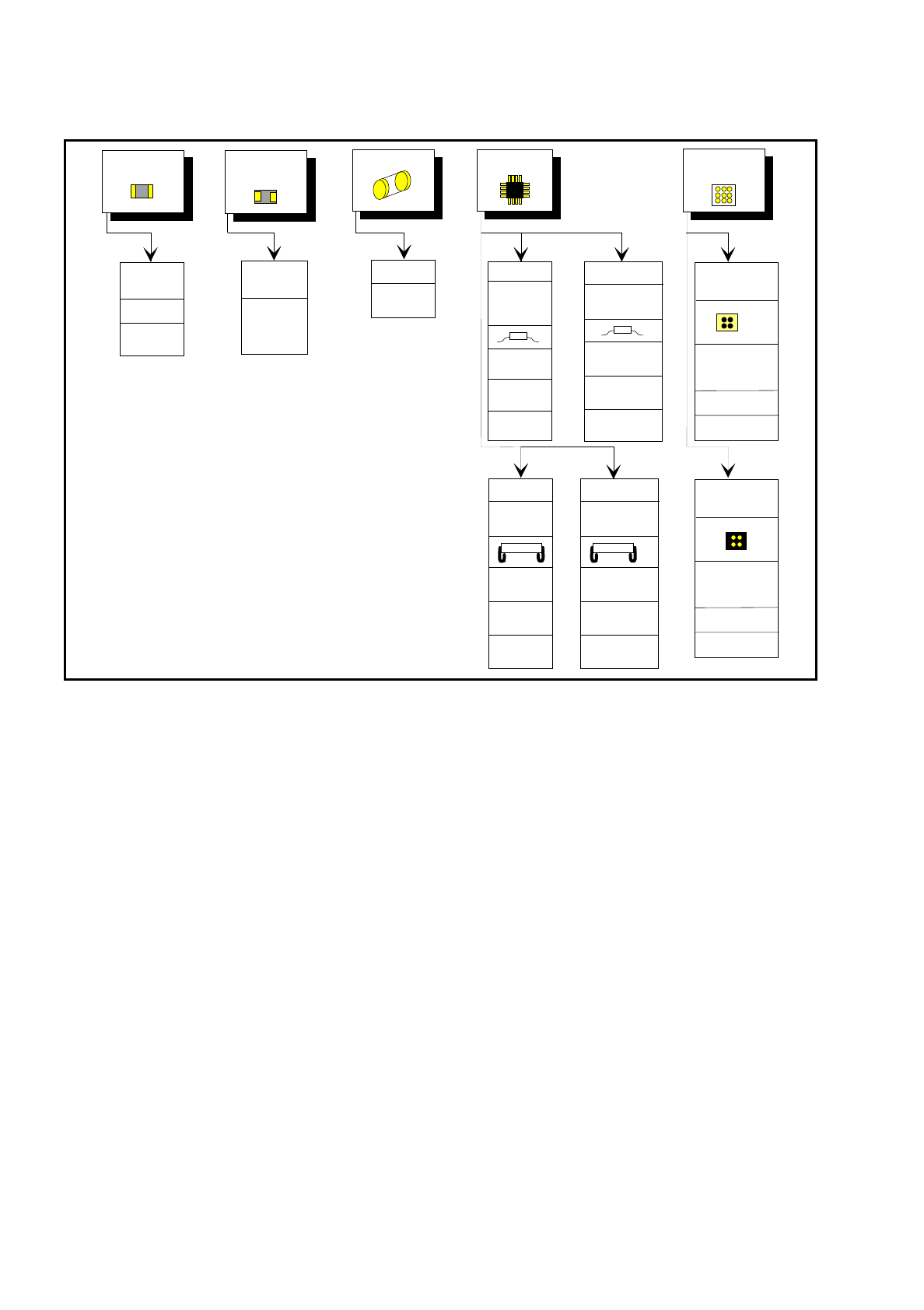
Fig 7.7.6 Typical measuring modes with standard components
7.7.6 Setting the Components Illumination at the Revolver Head Cam-
era
7.7.6.1 General Information on Illumination Methods
The idea of illumination setting is to obtain an image of the leads of a component which is as high-contrast as
possible. At the same time it is also important to suppress representation of the body of the component.
These instructions are intended to help you find the best possible illumination parameters. This, however,
does not imply that you rigidly comply with the values specified in these instructions. The way you should pro-
ceed is first to follow these instructions and then to adjust the parameters yourself where necessary. It may
well be that you come across one or other component the leads of which are better illuminated using values
different to the ones suggested in these instructions.
The illumination system comprises two different illumination levels. The intensities can be programmed indi-
vidually. By using the individual illumination levels one at a time or in combination with one another you can
adapt the illumination to suit a wide range of components.
Chip
IC
Melf
BGA
Flip chip
Tantal
capacitor
0402,
0603, etc.
General
SIZE
high
resolution
Small
Small
BGA
SIZE
LEAD
outer tip
SIZE
LEAD
outer tip
SIZE (depends
on the comp.
size)
SIZE
CORNER
outer tip
LEAD
outer tip
SOJ,
PLCC
SIZE
CORNER
Lead center
LEAD
Lead center
Large
Large
CORNER
outer tip
LEAD
outer tip
ROW
outer tip
SO,
QFP
PLCC
CORNER
Lead center
LEAD
Lead center
ROW
Lead center
GRID
BALL
SO, SOT
QFP
Flip Chip
SIZE (depends
on the comp.
size)
GRID
BALL