00191025-01.pdf - 第286页
7 Vision Systems SIPLACE 80S /F/G User’s Manual 7.6 Test Component Edition 07/97 f rom Software Version SR.010.xx 7 - 94 Line engine er 7.6.5.1 Dialog Boxes "Size", "Row", "Corner", "Le…
SIPLACE 80S/F/G User’s Manual 7 Vision Systems
Edition 07/97 from Software Version SR.010.xx 7.6 Test Component
Line engineer 7 - 93
7.6.4.5 Option “Program transform”
This option is analogous to the option “Program transform 5” in Section 7.5.5.2 and there described.
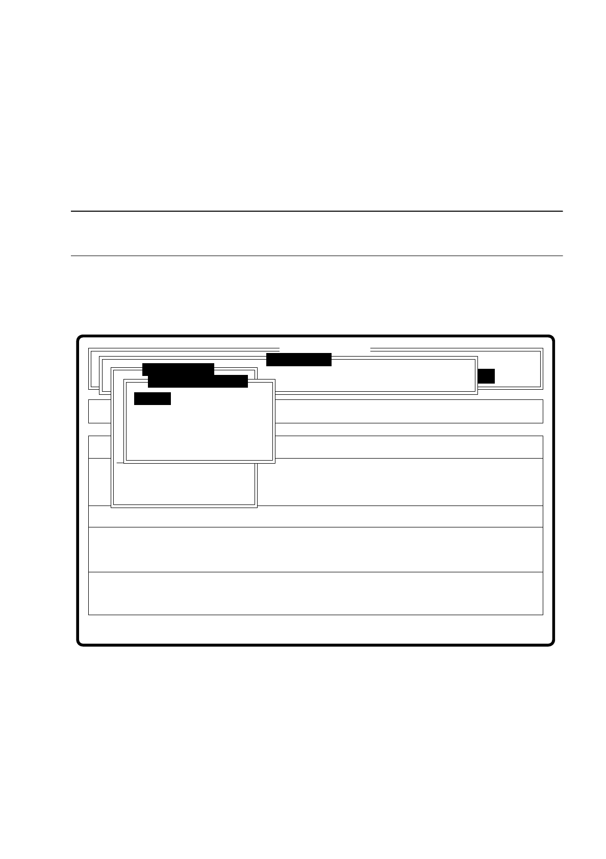
7.6.5 Menu “Change measure mode”
NOTE
The option can only be activated if a GF number has previously been entered.
In the sensor-specific part of the GF data (see Section 7.6.4) there is a data structure with measurement con-
ditions for the components. In this menu you can manipulate these measurement conditions. The menu
options are primarily intended for creating one's own user-specific GF files outside the standard GF file.
Fig. 7.6.22
The menu offers you the possibility of
–
selecting and activating a specific method of measurement or combination of several methods
–
deactivating measurement methods, and
–
modifying the hex parameters corresponding to each method of measurement.
Error
State
Action
Change measure mode Size
Rüstung:
Maschinenoptionen Single functions
Softwareoptionen
:
:
:
BE - Zuführung
Cluster:
SI80 V 10.x
Vision system
Vision system
Version: 2133
Setup:
Marke teachen
Test component
Refill
Display errors
Test output
Mess-Mode ändern
GF-Nr. eingeben
BE abholen
BE darstellen
BE prüfen
GF-Daten ändern
BE messen
Change measure mode
Row
Lead
Corner
Size
Grid
Ball
7 Vision Systems SIPLACE 80S/F/G User’s Manual
7.6 Test Component Edition 07/97 from Software Version SR.010.xx
7 - 94 Line engineer
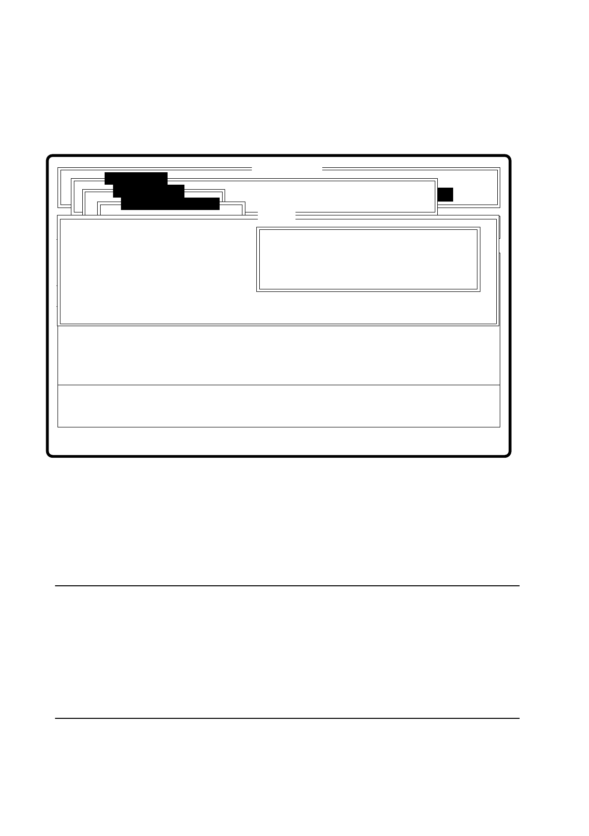
7.6.5.1 Dialog Boxes "Size", "Row", "Corner", "Lead", "Grid" and "Ball"
After a menu item has been selected the corresponding dialog window - "Size", "Row", "Corner", "Lead",
"Grid" or "Ball" opens. The "Corner" dialog window is shown as an example.
Fig. 7.6.23
●
With the Tab key you can toggle between option box and input box.
●
Use the arrow keys to position the cursor in the appropriate dialog box.
●
Use the space bar to mark in the option field the measurement method you have chosen. A cross is dis-
played to show that the option has been selected.
●
In the input field you can change the hex values of the measurement method and thus cater for the require-
ments of special components.
NOTE
Entering hex values presupposes considerable knowledge in measurement methodology. Explanatory
material in this connection goes beyond the scope of this operating manual. A detailed description will be
found, however, in the "MVS/EDA1 Application Manual". In this connection may we refer you in particular
to Sections III.7 "Electronic Device Alignment and Inspection: Implementation" and VII.4 "Electronic
Device Alignment and Inspection".
If you do intend to alter the hex values, then please contact the vision system development group and after
you have discussed the matter with them, enter the bit-coded hex values.
Error
State
Action
Change measure mode Corner
Rüstung:
Single functions
:
:
:
Nutzen:
SI80 V 10.x
Vision system
Vision system
Rüstung.
Test component
BE abholen
Size
Row
Lead
Corner
Change measure mode
( ) Corner driven
Esc: abort Blank: select Tab: change wind
CORNER P1 [ Hex ] :
CORNER P2 [ Hex ] :
CORNER P3 [ Hex ] :
CORNER P4 [ Hex ] :
CORNER P5 [ Hex ]:
Ret: input
Corner

SIPLACE 80S/F/G User’s Manual 7 Vision Systems
Edition 07/97 from Software Version SR.010.xx 7.6 Test Component
Line engineer 7 - 95
●
With “RETURN” close the dialog box. The modified measurement conditions are written to the GF file in
the station computer.
●
With “ESC” you can abort the dialog box without accepting data, then returning to the menu “Test compo-
nent”.
7.6.5.2 Information on the Measurement
With conventional components with lead connections, component centering is essentially based on four mea-
suring methods which aim at determining the position (x, y coordinates,
Φ
= angle of rotation) of the compo-
nent and the lead parameters:
–
Size-driven mode
–
Row-driven mode
–
Corner-driven mode
–
Lead-driven mode
For BGAs (Ball Grid Arrays) and flip chips new algorithms have been implemented for determining the position
(x, y coordinates,
Φ
= angle of rotation) of the component and the ball parameters (see also Section 7.6.3.4
Option “Measure component”):
–
Grid-driven mode
–
Ball-driven mode
Depending on your circumstances any method in this sequence can be omitted. But it is not possible to alter
their sequence.
Definition of the methods
●
Size-driven
This method was developed especially for small components. On the strength of the information on dimen-
sion parameters the position and rotation of small components is determined rapidly and reliably.
This procedure is very robust as regards defects such as color markings.
The size-driven method makes use of profile creation. It creates a profile either along the length
or
across
the width of the components. Whichever you selected can be marked in the option box with a cross. As
default the profile is always created for the longer side.
●
Row-driven
This method is based on the information for a pin row.
It is very fast and supplies approximate values for the coordinates and the angle of rotation of the compo-
nent.
●
Corner-driven (component inspection)
The measurement results provide precise information on the coordinates and rotation of the component,
the pin number, the spacing and of the row offset.
This method is not sensitive to variations in pin dimensions.