00191025-01.pdf - 第80页
5 Placement S IPLACE 80S/F/G User’s Manual 5.1 Introduction: Placement Edition 12/96 from Software Version S R.009.xx 5 - 4 Fig. 5.1.1 Flowchart: Placement Switch on - see Chapte r 3 Loading c luster data Settin g up the…

SIPLACE 80S/F/G User’s Manual 5 Placement
Edition 12/96 from Software Version SR.009.xx 5.1 Introduction: Placement
5 - 3
5.1 Introduction: Placement
5.1.1 General
The placement functions of the SIPLACE 80 F are identical with those of the SIPLACE 80 S. Section 5,
"Placement", of the user's manual, edition 06/96, applies for this reason to both machine types. However the
screen will show the actual machine designation. When the Siplace 80 F has additional or different functions
the corresponding section will include supplementary information. Differences can also exist in the software
version notice and in the header of the screen menus. This does not however have any influence on the func-
tions.
If, at a later point of time, additional function changes or additions with regard to the SIPLACE 80 S are real-
ized, Section 5 "Placement" will be revised accordingly.
5.1.2 Flow Diagram: Placement
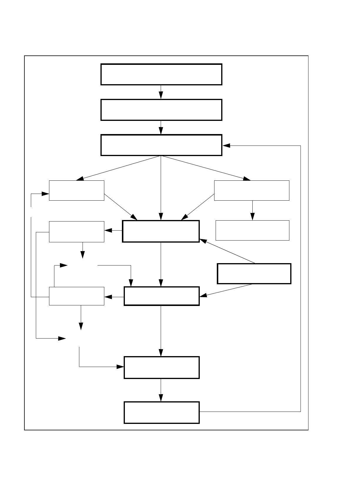
In the following Figure 5.1.1 the flow diagram for the function "Placement" is shown. This flow diagram applies
to both the SIPLACE 80 S and to the SIPLACE 80 F.
5 Placement SIPLACE 80S/F/G User’s Manual
5.1 Introduction: Placement Edition 12/96 from Software Version SR.009.xx
5 - 4
Fig. 5.1.1 Flowchart: Placement
Switch on - see Chapter 3
Loading cluster data
Setting up the machine according
to the placement program
Nozzle configuration
Component supply
(track assignment)
PCB handling
Changing nozzles
Fiducial error
Placement options
Placement
Track error
Machine error
Continue
placement
Track empty
Abort
placement
PCB to output conveyor
New cluster
SIPLACE 80S/F/G User’s Manual 5 Placement
Edition 12/96 from Software Version SR.009.xx 5.2 Loading Cluster Data
5 - 5
5.2 Loading Cluster Data
NOTE
The menus and activities described in this section are only needed and enabled when no line computer is
connected and when the function "without LC" has been selected in the selection menu "LC mode." If a line
computer is connected, cluster control is effected via the line computer.
5.2.1 Initial Loading of Cluster Data after Switching On the Machine
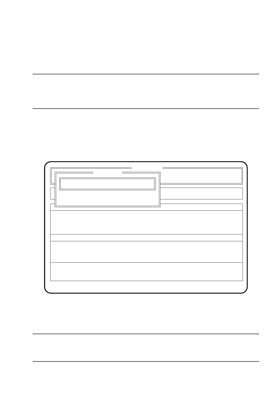
After the machine has started, the menu "New cluster" appears automatically.
Fig. 5.2.1
●
Using the keyboard, enter the name of the cluster which is to be processed.
●
Confirm the input using the
Return key
("State:" Wait for data).
NOTE
Set-up and cluster have to be present on the hard disk together with the corresponding package form and
fiducial data.
SI 80 V 9.x
Rüstung :
Machine options
Software options
Single functions
Vision system
Error
State
Action
:
:
:
Visionsystem
Neuer Nutzen...
Schnittst. GESP.
Cluster name: TEST
Esc: abort Ret: input
New cluster
New cluster ...
Wait for data