00191025-01.pdf - 第211页
SIPLACE 80S/F/G User’s Manual 7 Vision Systems Edition 07/97 from S oftware Version SR.010.xx 7.2 PCB Vision System Line engi neer 7 - 19 – Space between li nes (a) The sp ace between the li nes also depen ds on the type…
7 Vision Systems SIPLACE 80S/F/G User’s Manual
7.2 PCB Vision System Edition 07/97 from Software Version SR.010.xx
7 - 18 Line engineer
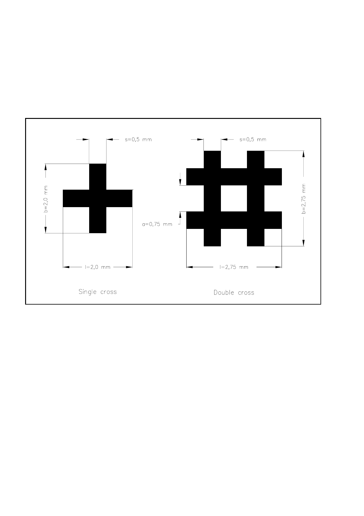
Characteristics of the single cross
–
Information content somewhat lower than with the double cross
–
Needs less space in the layout than the double cross
–
Less sensitive than the double cross where there is high tinning
Dimensions of the fiducials:
Single and double cross
Fig. 7.2.3 Single and double crosses with ideal dimensions
The minimum dimensions for a fiducial as regards length (l) and width (b) will depend on the line thickness
(s) and the structure of the fiducial.
–
length (l) and width (b)
For good recognition of a fiducial the length and the width should be at least 0.9 mm with the single
cross and 1.8 mm with the double cross. The ideal dimensions for the single cross are 2.0 mm and for
the double cross 2.75 mm. Under normal circumstances length and width are equal.
–
line thickness (s)
The line thickness can vary according to standard structure widths and will depend on the type of fidu-
cial. Make sure however that the line thickness is always greater than 0.3 mm. The ideal line thickness
for both fiducial types is 0.5 mm.

SIPLACE 80S/F/G User’s Manual 7 Vision Systems
Edition 07/97 from Software Version SR.010.xx 7.2 PCB Vision System
Line engineer 7 - 19
–
Space between lines (a)
The space between the lines also depends on the type of fiducial. It should never be less than 0.5 mm.
With the double cross the ideal spacing should be 0.75 mm.
–
Thickness (d)
Especially with tin fiducials you should make sure that warping does not exceed 1/10 of the width of
the structure. If warping exceeds this it could happen that the fiducial is not evenly illuminated. The
results are different reflection behavior and interference reflections. Recognition of the fiducials is then
no longer guaranteed.
Recommended fiducial dimensions
Evaluation of fiducial shapes
With tinned structures and higher dimensional stability (lower etching fluctuations) full circles or complete
squares can be regarded as very suitable shapes for fiducials (ratio of fiducial thickness to presoldering thick-
ness is high!). If dimensional stability falls, the full circle is to be preferred to the square.
As far as single and double cross fiducial shapes are concerned bright copper is advantageous provided that
oxidation is not yet far advanced.
●
Fiducial surface
Make sure that the fiducial surface is as even as possible and with little oxidation. Avoid wetting the fiducial
with solder resist as this will reduce the contrast with the background or interference reflections may occur.
Similar effects occur with tinned fiducials also.
●
Contrast of the fiducials
To ensure that fiducial recognition is of a high quality select a high brightness contrast between the fiducial
and the base material, i.e. bright fiducials on dark base material or vice versa. For example, apply dark
fiducials on a copper or tin background. In the case of ceramics substrates with a bright surface and unfa-
vorable reflection characteristics it often helps to place dark resistance material underneath, in order to
improve contrast.
Fiducial type Single cross Double cross
Range Ideal range Range Ideal range
Length (l) 0.9 mm (min) 2.0 mm 1.8 mm 2.75 mm
Width (b) 0.9 mm (min) 2.0 mm 1.8 mm 2.75 mm
Line thickness (s) 0.3 - 1.5 mm 0.5 mm 0.3 - 0.75 mm 0.5 mm
Line spacing (a) — — 0.5 mm (min) 0.75 mm
Thickness (d) < 1/10 of the width of the structure < 1/10 of the width of the structure

7 Vision Systems SIPLACE 80S/F/G User’s Manual
7.2 PCB Vision System Edition 07/97 from Software Version SR.010.xx
7 - 20 Line engineer
●
Number of fiducials
When ceramic substrates and small PCBs are used it is usually adequate to apply two fiducials. It is how-
ever recommended with larger boards to define three fiducials. The individual fiducials may exhibit different
structures. They do however simplify recognition methods when the same structure is used for each fidu-
cial.
–
Correction with two fiducials x position
y position
twisting of the board
–
Correction with three fiducials: Ideally the straight lines drawn through each two fiducial centers
lie parallel to the x and y axes
x position
y position
twisting of the board
shear
warping of the PCB in x direction
warping of the PCB in y direction
NOTE
Under no circumstances should you position 3 fiducials so that they lie on one straight line.
●
Spacing between the fiducials
The fiducials can be distributed over the board at random. It is however a good idea for the spacing
between the fiducials to be as large as possible on both axes. The further apart the fiducials are, the more
precisely the position and angle can be determined optically.