00191025-01.pdf - 第263页
SIPLACE 80S/F/G User’s Manual 7 Vision Systems Edition 07/97 from S oftware Version SR.010.xx 7.6 Test Co mponent Line engi neer 7 - 71 The ope rator can now v isually che ck the syn thetic desc ription for agreement w i…
7 Vision Systems SIPLACE 80S/F/G User’s Manual
7.6 Test Component Edition 07/97 from Software Version SR.010.xx
7 - 70 Line engineer
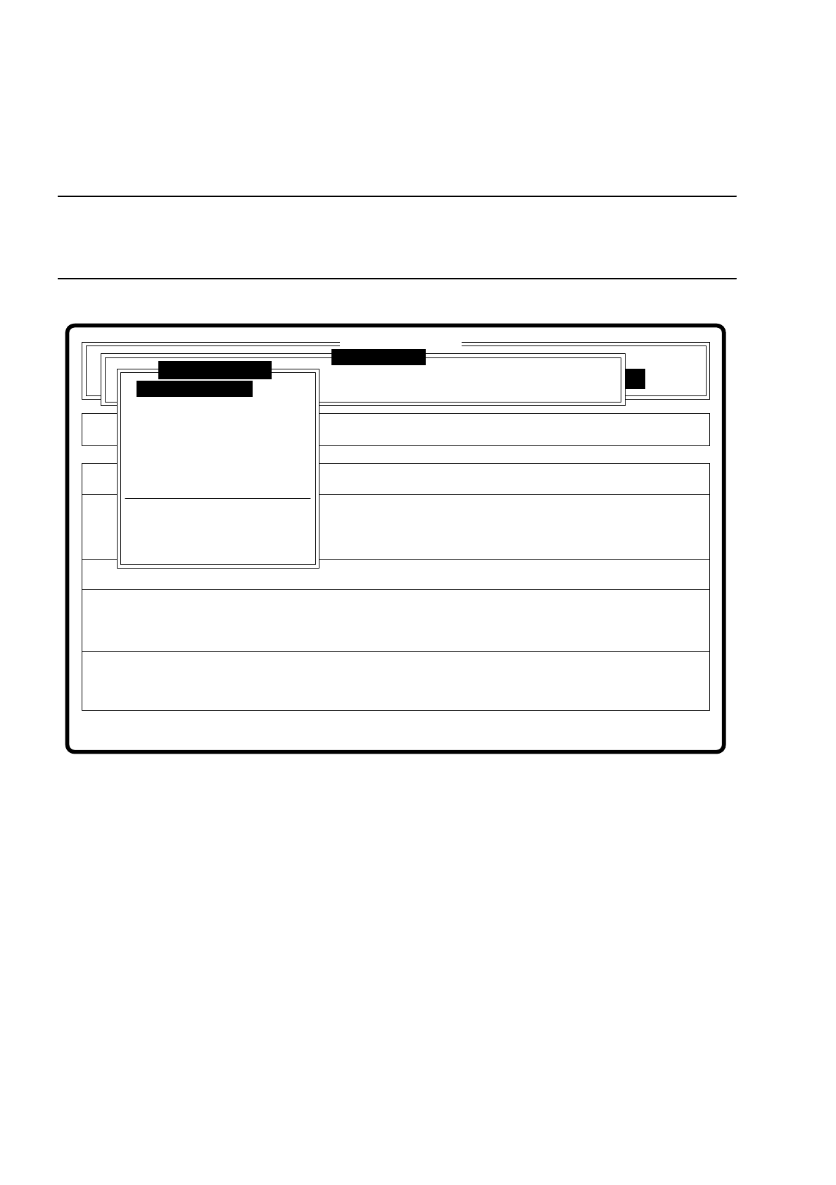
7.6.3.3 Option “Display component”
NOTE
Before you activate this option, a component must already be under the component camera. In addition, a GF
number must already have been entered.
Fig. 7.6.7
When this option is activated the following actions are initiated:
–
The teach command is initiated.
–
The vision system generates the external contours of the component from the synthetic description
–
The video image with the real camera image and the model superimposed on it is displayed on the screen.
–
The top line with comments is also displayed.
Error
State
Action
Enter package form number
Rüstung:
Single functions
:
:
:
BE - Zuführung
SI80 V 10.x
Vision system
Vision system
Vision system
Version: 2133
Test component
Enter GF number
Pickup component
Display component
Measure component
Test component
Edit GF data
Change measure mode
Refill
Display errors
Test output
SIPLACE 80S/F/G User’s Manual 7 Vision Systems
Edition 07/97 from Software Version SR.010.xx 7.6 Test Component
Line engineer 7 - 71
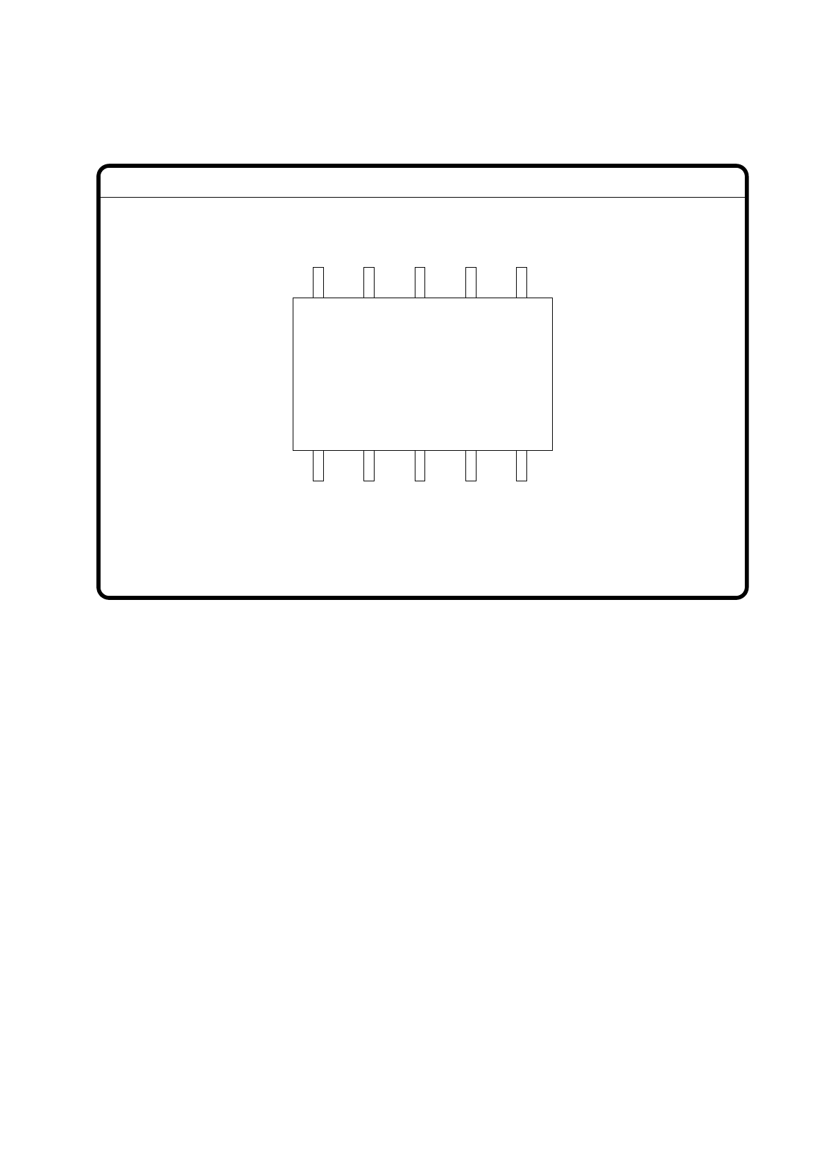
The operator can now visually check the synthetic description for agreement with the real image.
Fig. 7.6.8
With “ESC” you can terminate the function. The video image disappears and the menu “Test component” is
displayed once again.
GF No. = 5Display component
7 Vision Systems SIPLACE 80S/F/G User’s Manual
7.6 Test Component Edition 07/97 from Software Version SR.010.xx
7 - 72 Line engineer
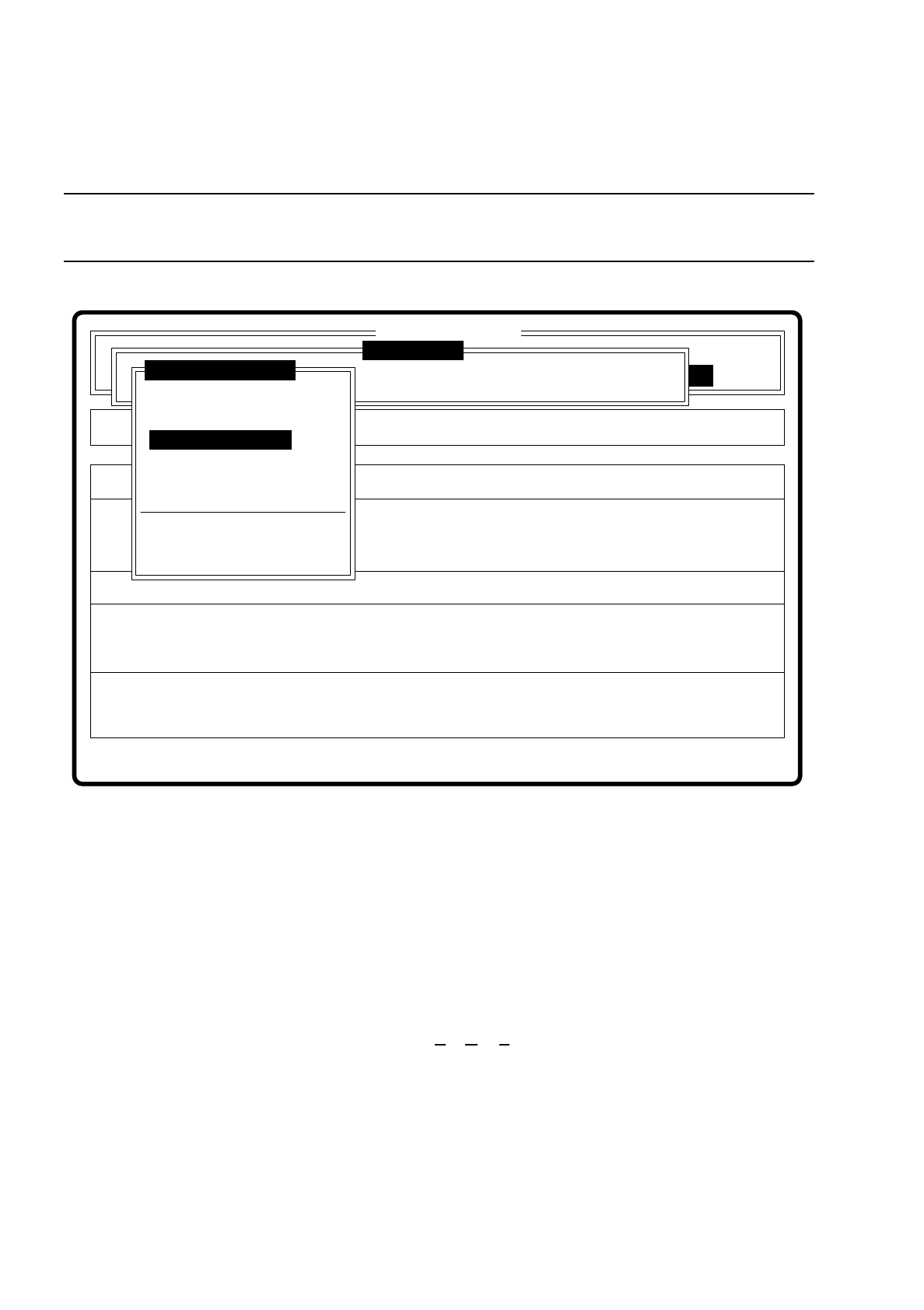
7.6.3.4 Option “Measure component”
NOTE
This option is only activated when a GF number has previously been entered.
Fig. 7.6.9
When this option is activated the following actions are initiated:
–
The video image is displayed on the screen.
–
The measurement command is initiated with the predefined parameters.
–
The MVS executes the component-specific measurement steps one after the other.
–
The measured values are superimposed on the video image.
With the Siplace 80F machine from software version 7.x onwards, in addition to conventional components with
leads it will also be possible to optically center BGAs (B
all Grid Arrays), and from software version 8.x flip
chips as well. The component body of the BGAs and flip chips consists of passivated silicon chips. These chip
bodies reflect strongly and are wavy. The connections of these components take the form of solder balls with
a diameter of at least 80
µ
m. With ball grid arrays the connections are arranged in the form of a grid, which
means that they can be described in terms of rows and columns.
With flip chips the solder balls are located irregularly over the body of the component. For this reason the
coordinates of each lead must be determined individually.
Error
State
Action
Measure component
Single functions
:
:
:
Cluster:
SI80 V 10.x
Vision system
Vision system
Vision system
Version: 2133
Setup:
Test component
Enter GF number
Pickup component
Display component
Measure component
Test component
Edit GF data
Change measure mode
Refill
Display errors
Test output