00191025-01.pdf - 第17页
SIPLACE 80S/F/G User’s Manual 0 Introduction Edition 07/97 from S oftware Version SR.010.xx 0.2 Technical Data 0 - 13 0.2.2 SIPLACE 80F 0.2. 2.1 Gantr y Axis 0.2.2.2 Revolve r Head Noise e mission values specified in a c…
0 Introduction SIPLACE 80S/F/G User’s Manual
0.2 Technical Data Edition 07/97 from Software Version SR.010.xx
0 - 12
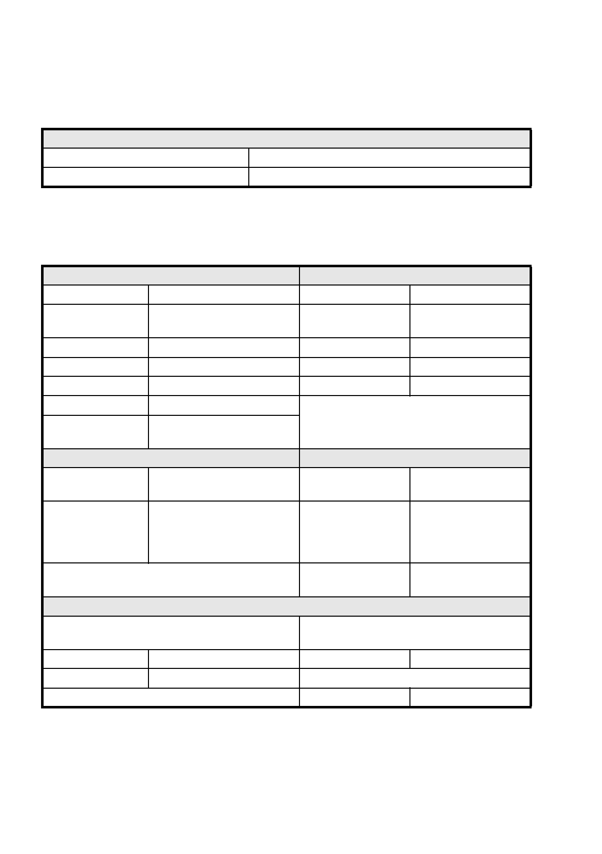
0.2.1.5 Interfaces 80S
0.2.1.6 Connection and Installation Data 80S
Interfaces 80S
Electrical Siemens handshaking interfaces in the placement machines
Mechanical Conveying height: 830 mm ± 15 mm
Connection and Installation requirements Machine dimensions
System voltage 230/400V ± 10 % (50/60 Hz) Weight base module 1500 kg
System voltage
opt. e.g. for USA
110/208 V ± 10 % (50/60 Hz) Weight fully-equipped 2000 kg
Total connected load 5 kVA Length 1587 mm
Total output 5 kW Width 2425 mm
Fuse protection 3 x 16 A Height with warning light 1836 mm
Compressed air supply At least 6 bar 600 NL/min.
Machine footprint
Permissible surface load
> 1 t/m²
Permissible environmental influences Machine control
Room temperature Between 15°C and 35°C Control computer
PC 386,
RMOS operating system
Air humidity
30 to 75 % (on average not higher
than 45 %, so that under no cir-
cumstances will there be conden-
sation in or on the machine
Machine control
SIMICRO
Input / output control
Axis controller
Siemens axis controller
boards (digital)
Compressed air specification
Max. particle size by density, based on ISO/DIS 8573-1
(Class 1)
Maximum oil content
Class 1
Particle size 0.1 µm Particle density 0.01 mg/m³
Particle density 0.1 mg/m³ Pressure dewpoint Class 4
Dewpoint + 3°C
SIPLACE 80S/F/G User’s Manual 0 Introduction
Edition 07/97 from Software Version SR.010.xx 0.2 Technical Data
0 - 13
0.2.2 SIPLACE 80F
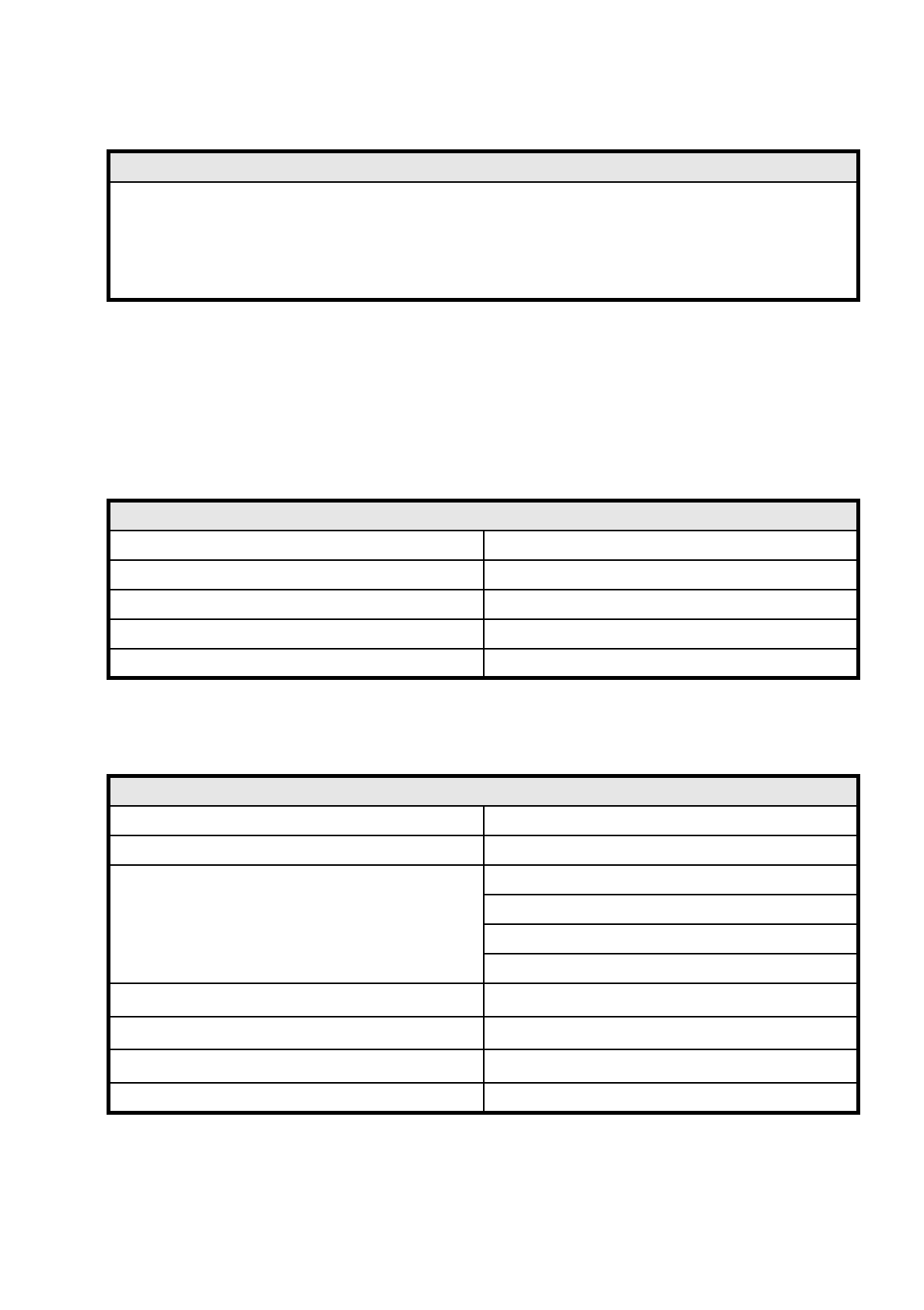
0.2.2.1 Gantry Axis
0.2.2.2 Revolver Head
Noise emission values specified in accordance with DIN 45 649-1
Emission value at a workstation (L
pAc
) 70 dB (A)
DIN EN ISO 11204 (i)
Sound power level (L
WAc
) 84 dB (A)
E-DIN EN ISO 3744 (i)
353-9217
Gantry axes 1 and 2
Drive D.C. servo motors
Path-measuring system Linear incremental scales
Resolution x / y axes 2.5
µ
m
Max. speed x axis 2.0 m/s
Max. speed y axis 2.5 m/s
Revolver head 80F
Programmable placement force (z axis) 2.4 to 4.0 N
Nozzle types 8
Components to be assembled
Max. height 6.0 mm
Min. pitch 0.5 mm
Dimensions: 0.5 mm x 1.0 mm to 14 mm x 18 mm
Weight up to 2 grams
Path dp1/dp2 turning axes
± 180
o
Resolution dp1/dp2 turning axes
0.10
o
Resolution star head axis
0.005
o
Z axis stroke 14 mm
0 Introduction SIPLACE 80S/F/G User’s Manual
0.2 Technical Data Edition 07/97 from Software Version SR.010.xx
0 - 14
0.2.2.3 IC Head
0.2.2.4 CRDL Tester 80F
See Section 0.2.1.3 CRDL Tester 80S
0.2.2.5 Boards, Components, Tapes (80F)
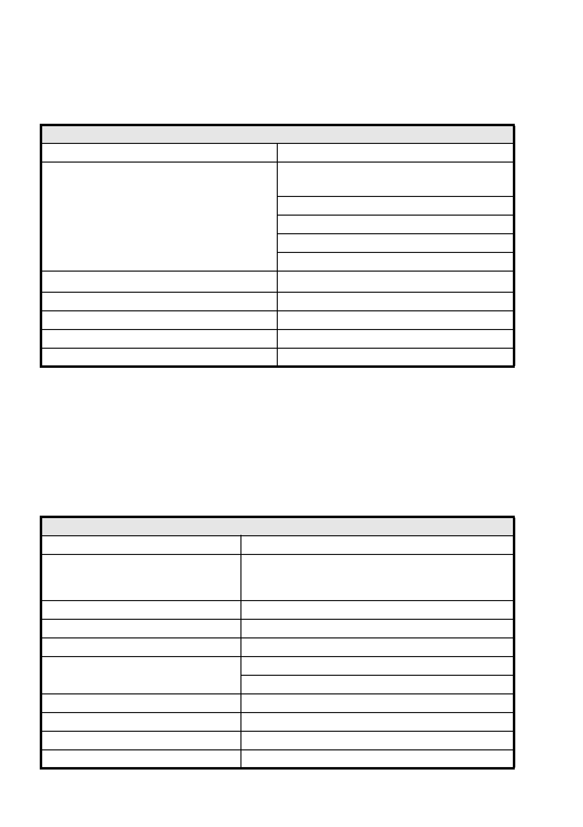
IC head
Number 1
Components to be assembled
Max. height:
PCB
thickness
+ PCB
warpage
+ Comp.
height
≤
13.5 mm
Min. height: 0.3 mm
Min. pitch: 0.4 mm
Dimensions: up to 55 mm x 55 mm (larger on request)
Weight up to 25 grams
Resolution of the d axis
0.005
o
Z axis stroke 50 mm
Programmable placement force (z axis) 1.0 to 10.0 N
Nozzle types 4
Component centering Fine pitch vision module
Boards, components, tapes (80F)
Boards (PCB) transport system In-line transport with width adjustment
PCB format
50 mm x 50 mm to 460 mm x 460 mm with PCB buffer
50 mm x 50 mm to 508 mm x 460 mm
without PCB buffer (upon request)
Component-free guide edge of the board 3 mm
Min. PCB thickness 0.5 mm
Max. PCB thickness 4.5 mm
Max. PCB warpage
Upwards : 4.5 mm less PCB thickness
Downwards: 0.5 mm plus PCB thickness
PCB change time 2.5 sec.
Max. number of 8 mm tapes 80
Tape reel diameter Max. 15" in the reel container
Component range 0402 to 55 mm x 55 mm (larger on request)