00191025-01.pdf - 第279页
SIPLACE 80S/F/G User’s Manual 7 Vision Systems Edition 07/97 from S oftware Version SR.010.xx 7.6 Test Co mponent Line engi neer 7 - 87 7.6.3.10 Option "Test O utput" The "Tes t output" option is in t…

7 Vision Systems SIPLACE 80S/F/G User’s Manual
7.6 Test Component Edition 07/97 from Software Version SR.010.xx
7 - 86 Line engineer
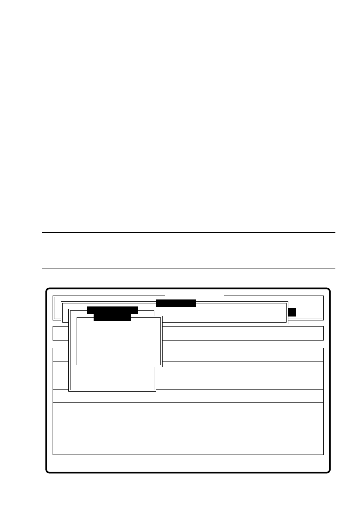
7.6.3.9 Menu “Display errors”
Fig. 7.6.16
The menu “Display error” and its options
–
Track error
–
Transport error
–
Machine error
–
General error
pop up when selected.
Key functions
–
With the
cursor keys
↑
and
↓
you can scroll through the display line by line.
–
With the keys
PgUp
and
PgDn
you can move through the display page by page.
–
With the key
Home
you can jump to the beginning of the display, and with the key
End
to the last item in the
display.
–
With the key
ESC
you may quit the menu. The menu which you used to call the menu "Confirm error" is
displayed on the screen.
A description of the menu will be found in Section 5.6 “Display functions” of this user’s manual.
Error
State
Action
Display error list separately according to error types
Rüstung:
Single functions
:
:
:
Cluster:
SI80 V 10.x
Vision system
Vision system
Vision system
Version: 2133
Setup:
Test component
Enter GF number
Pickup component
Display component
Measure component
Test component
Edit GF data
Change measure mode
Refill
Display errors
Test output
SIPLACE 80S/F/G User’s Manual 7 Vision Systems
Edition 07/97 from Software Version SR.010.xx 7.6 Test Component
Line engineer 7 - 87
7.6.3.10 Option "Test Output"
The "Test output" option is intended as a development tool. When you have problems with a package form,
print out the results of optical centering and contact the vision system development group.
7.6.4 Menu “Edit GF data”
The GF ("Gehäuse-Form" = package form) file is stored in the line computer. It basically consists of two main
parts:
–
the geometric package form data and
–
the sensor-specific data
The sensor specific part contains the
–
measurement conditions for the component
–
the type of illumination and the
–
transformation table data
NOTE
The menu “Edit GF data” is only activated if you have already entered a GF number. If not, a message is dis-
played which asks you to enter a GF number. When you have done so, the menu pops up.
Fig. 7.6.17
Error
State
Action
Change dimension of a pin (optical length and width)
Machine options Single functions
Softwareoptionen
BE - Zuführung
Cluster:
SI80 V 10.x
Vision system
Vision system
Vision system
Setup:
Version: 2133
Meßmodus ändern
GF-Nr. eingeben
BE abholen
BE darstellen
BE messen
BE prüfen
GF-Daten ändern
Pin dimension
Package dimension
Ball image
Illumination
Program transform 5
Edit GF data
Test component
Refill
Display errors
Test output
:
:
:

7 Vision Systems SIPLACE 80S/F/G User’s Manual
7.6 Test Component Edition 07/97 from Software Version SR.010.xx
7 - 88 Line engineer
In this menu you have the possibility of changing
–
the pin dimensions,
–
the package dimensions,
–
the ball image parameter,
–
the illumination parameters, and
–
the transformation table.
●
Pin dimension parameters are
–
optical pin length along the x and y axes of the components
–
optical pin width along the x and y axes of the components
–
spacing of the pins along the x and y axes of the component. By spacing is meant the distance from
the center of one pin to the center of the next pin.
–
Number of pins along the x and y axes of the component
NOTE
The spacing and the pin number can only be altered at the line computer.
●
Package dimension parameters are
–
the external dimensions of the component in millimeters along the x and y axes. By external dimen-
sions is meant the optical dimensions of the component including pin dimensions.
The geometric dimensions of pins and component are stored in the line computer in the GF file. Depending
on the geometry of the component and the illumination by the component camera image defects may
occur. The image does not reproduce the real geometric dimensions - the image is reduced. This is termed
imaging reduction. Thus one refers to the optical dimensions of pin and component. The reduction factor
for every pin dimension / package form is entered in the GF file in the line computer and can be changed
using this menu.
As regards the position definition of the coordinate axes and the definition of regular or irregular components,
please refer to Section 7.3.3.
●
Ball image parameters are
–
internal, external radius type
–
internal, external radius
–
contrast
–
ball model
●
Illumination parameters are
–
the contrast in the image
–
the selection of the top or bottom LED row for steep or shallow-angled illumination of the component
(brightness control).