00191025-01.pdf - 第264页
7 Vision Systems SIPLACE 80S /F/G User’s Manual 7.6 Test Component Edition 07/97 f rom Software Version SR.010.xx 7 - 72 Line engine er 7.6.3.4 Option “Measure com ponent” NOTE This op tion is onl y activated when a GF n…
SIPLACE 80S/F/G User’s Manual 7 Vision Systems
Edition 07/97 from Software Version SR.010.xx 7.6 Test Component
Line engineer 7 - 71
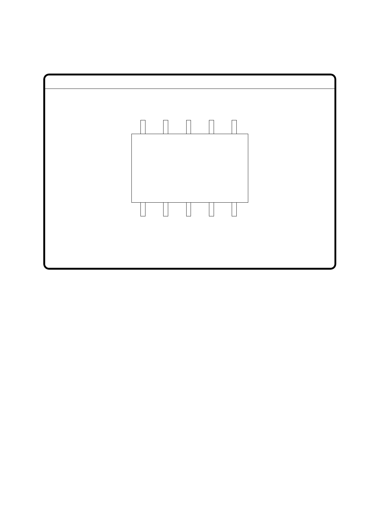
The operator can now visually check the synthetic description for agreement with the real image.
Fig. 7.6.8
With “ESC” you can terminate the function. The video image disappears and the menu “Test component” is
displayed once again.
GF No. = 5Display component
7 Vision Systems SIPLACE 80S/F/G User’s Manual
7.6 Test Component Edition 07/97 from Software Version SR.010.xx
7 - 72 Line engineer
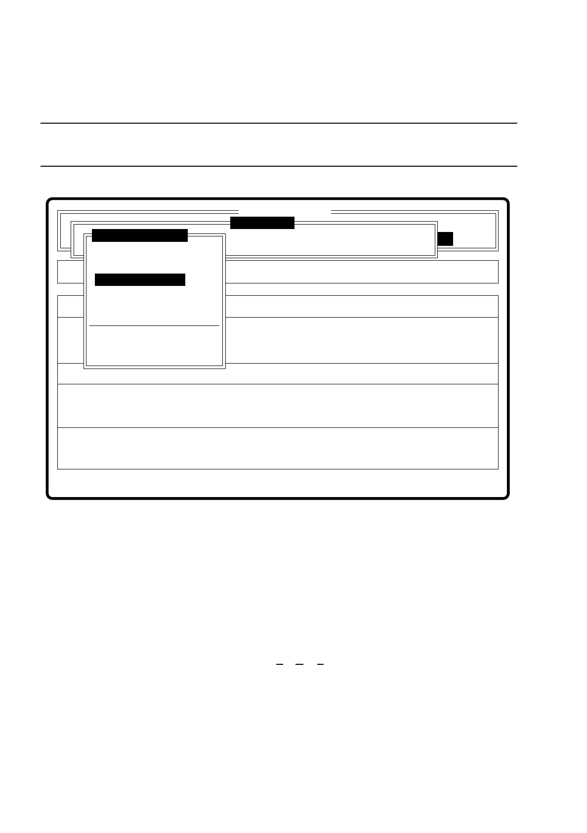
7.6.3.4 Option “Measure component”
NOTE
This option is only activated when a GF number has previously been entered.
Fig. 7.6.9
When this option is activated the following actions are initiated:
–
The video image is displayed on the screen.
–
The measurement command is initiated with the predefined parameters.
–
The MVS executes the component-specific measurement steps one after the other.
–
The measured values are superimposed on the video image.
With the Siplace 80F machine from software version 7.x onwards, in addition to conventional components with
leads it will also be possible to optically center BGAs (B
all Grid Arrays), and from software version 8.x flip
chips as well. The component body of the BGAs and flip chips consists of passivated silicon chips. These chip
bodies reflect strongly and are wavy. The connections of these components take the form of solder balls with
a diameter of at least 80
µ
m. With ball grid arrays the connections are arranged in the form of a grid, which
means that they can be described in terms of rows and columns.
With flip chips the solder balls are located irregularly over the body of the component. For this reason the
coordinates of each lead must be determined individually.
Error
State
Action
Measure component
Single functions
:
:
:
Cluster:
SI80 V 10.x
Vision system
Vision system
Vision system
Version: 2133
Setup:
Test component
Enter GF number
Pickup component
Display component
Measure component
Test component
Edit GF data
Change measure mode
Refill
Display errors
Test output

SIPLACE 80S/F/G User’s Manual 7 Vision Systems
Edition 07/97 from Software Version SR.010.xx 7.6 Test Component
Line engineer 7 - 73
The IC head of the 80F machine picks up the BGAs or flip chips from the flatpack magazines. However the
evaluation procedures which have been used so far for conventional components are no longer adequate for
optical centering of BGAs and flip chips. For this reason new evaluation procedures and new lighting methods
at the IC sensor and/or FC sensor have been developed to make it possible to center optically this new gener-
ation of components. BGAs and flip chips which cannot be optically centered will be returned to the flatpack
magazine by the IC head for further analysis.
Fig. 7.6.10
Optical gauging of conventional components with lead connections in the 80S and 80F placement
machine
The crosshairs show the center of gravity of the component. The component outlines are emphasized by
color.
The measured values represent the geometric component parameters such as
–
Pin deviation
The value for the lead deviation is output if you have selected the "Lead-driven" measurement mode.
–
Spacing
The value is output if the "Corner-driven" measurement mode is active as the last measurement step.
–
Number of pins
–
x / y offset
–
Orthogonality
Measure component
GF No. = 5
X offset = ... Y offset = ...
Phi = ...
Orthogon = ...
No. of pins = ...
Quality fact. = ...
Length[mm] = ...
Width[mm] = ...
Spacing[mm] =
RET: Measure component
P.dev.[mm] =