00198439-03_SIPLACE_JTF-ML2_TX12_V1-V2_DE_EN_CHS.pdf - 第122页
4 Setting up and commissioning 4.2 Retrofitting in the SIPLACE TX-Series 122 User Manual / Bedienungsanleitung / 用户手册 SIPLACE TX V1/V2 Series JEDEC Tray Feeder (JTF-ML2) 11/2019 4.2 Retrofitting in the SIPLACE TX-Series …
4 Setting up and commissioning
4.1 Requirements and restrictions
User Manual / Bedienungsanleitung / 用户手册 SIPLACE TX V1/V2 Series JEDEC Tray Feeder (JTF-ML2) 11/2019 121
4 Setting up and commissioning
NOTICE
Example shown as diagram
The following diagrams are just examples. The procedure is the same for other machine
types than the SIPLACE TX1 / TX2-V1 / V2 shown. Any relevant differences will be men-
tioned explicitly.
4.1 Requirements and restrictions
The following requirements and restrictions apply to the SIPLACE JTF-ML2:
●
Assembly is only possible on SIPLACE TX1 and TX2 machines.
Assembly is not possible on SIPLACE TX2i machines.
●
The software version of a SIPLACE TX1/TX2 V1 machine must be 710.1 or higher. The soft-
ware version of a SIPLACE TX1/TX2 V2 machine must be 711.1 or higher.
●
The assembly is only possible at location 1.
●
The conveyor and the tower of the SIPLACE JTF-ML2 have the same ID number and must al-
ways be working as a pair.
It is not allowed to use a conveyor and a tower with different ID numbers.
Placement Heads
The following placement heads are possible:
●
CPP_H
●
TwinHead
From SIPLACE TX V2:
●
C&P20 P2
●
CPP_L
●
CPP M
Information on additional placement head variants are available upon request.
Also observe: 2.1.5 "Risk of crashing when using thick JEDEC trays" [}108]
Trays
NOTICE
Magnets with reduced height for Cookie Trays
When using magazine sheets (Cookie Trays), magnets with reduced height are required
[03160331‑xx]. For details, refer to the Technical Information "Magnet for JTF-ML2 Cookie
Tray" [DE:TI2019‑06D01] [EN:TI2019‑06E01].
4 Setting up and commissioning
4.2 Retrofitting in the SIPLACE TX-Series
122 User Manual / Bedienungsanleitung / 用户手册 SIPLACE TX V1/V2 Series JEDEC Tray Feeder (JTF-ML2) 11/2019
4.2 Retrofitting in the SIPLACE TX-Series
4.2.1 Scope of delivery for retrofitting in the SIPLACE TX-Series V1
The following parts are required for retrofitting in the SIPLACE TX-Series V1:
●
SIPLACE JTF-ML2 (tray feeder module) [00588116‑xx]
●
Changeover table for SIPLACE JTF-ML [00588112‑xx]
●
Assembly kit for SIPLACE JTF-ML2 [00588117S‑xx]
Additionally required parts on a SIPLACE TX V1:
●
Magazine sheet for SIPLACE JTF-M magazines [03110222Sxx]
●
If you fit the SIPLACE JTF ML2 to a SIPLACE TX V1 with a CPP head, the "Reject box /
nozzle station IC-camera V1"[03162806-xx] and the "Nozzle station CPx cpl. / X4iS,
XS" [03090348-xx] must be ordered in addition!
Assembly kit for SIPLACE JTF-ML2 (SIPLACE TX V1)
Count Designation Item no.
1 SIPLACE JTF-ML2 adapter for SIPLACE TX machine complete 03129004‑xx
1 Empty tape duct, short TX assembly 03121376-xx
1 Mounting support TX-JTF assembly 03136824-xx
1 Cable COTi TX: DC control to SIPLACE JTF-ML 03134469-xx
1 Cable COTi TX: CAN bus3 to SIPLACE JTF-ML 03134468-xx
1 Cover assembly for SIPLACE JTF complete 03119382-xx
1 Dummy feeder 12 tracks 03154408- xx
1 Cable: Power Adapter JTF 03160347- xx
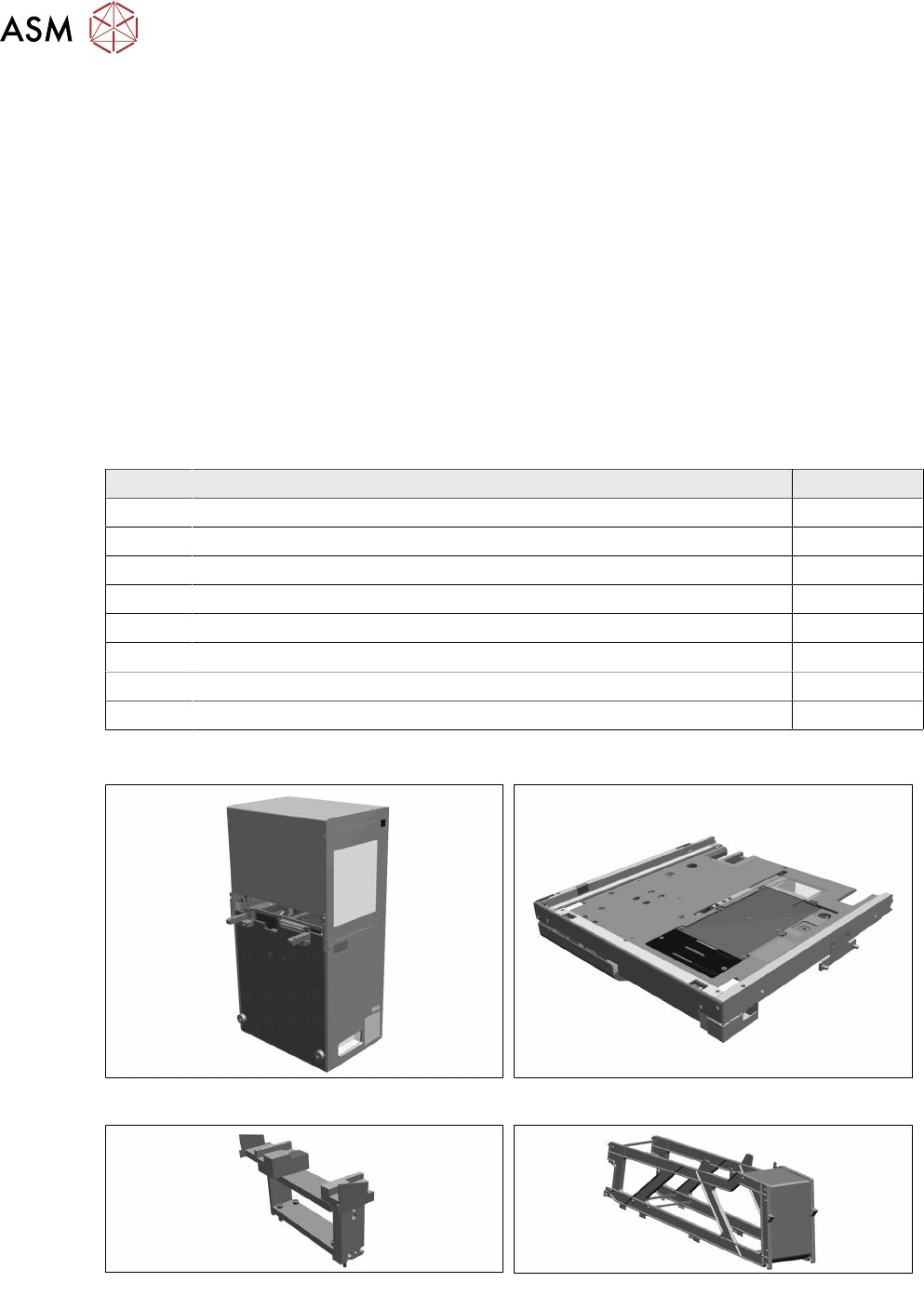
4.2.1.1 Overview of Parts
Fig.23: SIPLACE JTF-ML2 tower
Fig.24: SIPLACE JTF-ML2 conveyor
Fig.25: SIPLACE JTF-ML2 adapter
Fig.26: Dummy feeder 12 tracks
4 Setting up and commissioning
4.2 Retrofitting in the SIPLACE TX-Series
User Manual / Bedienungsanleitung / 用户手册 SIPLACE TX V1/V2 Series JEDEC Tray Feeder (JTF-ML2) 11/2019 123
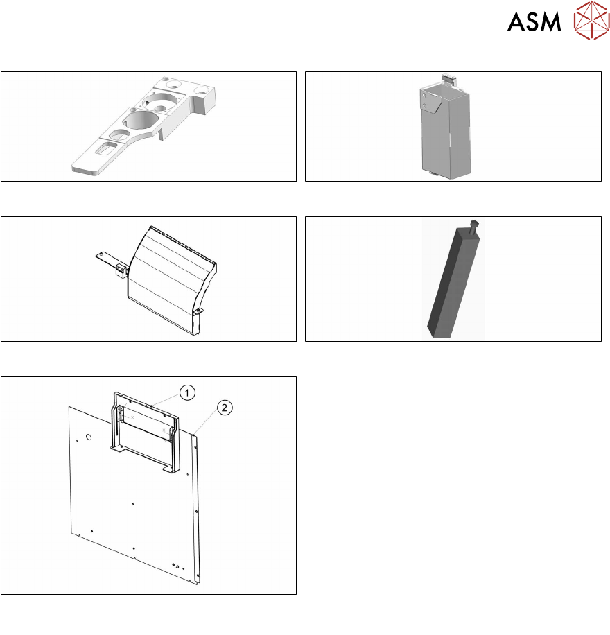
Fig.27: Nozzle station. IC camera V1 (optional)
Fig.28: Reject box
Fig.29: Empty tape duct, short SIPLACE TX assembly
Fig.30: Mounting support SIPLACE TX-JTF assembly
Fig.31: Cover assembly for SIPLACE JTF-ML/ML2
complete
Cover assembly for SIPLACE JTF-ML/ML2
complete
Consists of:
1. Support frame assembly location 1 for
SIPLACE JTF-ML/ML2 complete
2. Cover assembly on output side location 1,
TX