00198439-03_SIPLACE_JTF-ML2_TX12_V1-V2_DE_EN_CHS.pdf - 第135页
4 Setting up and commissioning 4.2 Retrofitting in the SIPLACE TX-Series User Manual / Bedienungsanleitung / 用户手册 SIPLACE TX V1/V2 Series JEDEC Tray Feeder (JTF-ML2) 11/2019 135 Fig.68: Inserting the support and remove …
4 Setting up and commissioning
4.2 Retrofitting in the SIPLACE TX-Series
134 User Manual / Bedienungsanleitung / 用户手册 SIPLACE TX V1/V2 Series JEDEC Tray Feeder (JTF-ML2) 11/2019
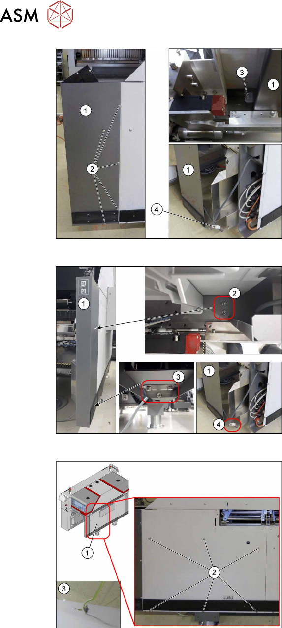
Fig.65: Removing the corner cover on the SIPLACE TX V1
SIPLACE TX V1:
Remove the corner cover(1). To do so, pro-
ceed as follows:
► Remove the screws(2) on the outer
side.
► Remove the screw(3) on the inner
side.
Hold the corner cover firmly while doing
this, so that it does not accidentally fall
down.
► Unplug the connector(4) and place the
corner cover(1) to one side.
Fig.66: Removing the corner cover on the SIPLACE TXV2
SIPLACE TX V2:
Remove the corner cover(1). To do so, pro-
ceed as follows:
► Remove the screws(2) on the inner
side.
► Remove the screws(3) on the bottom
side.
Hold the corner cover firmly while doing
this, so that it does not accidentally fall
down.
► Unplug the connector(4) and place the
corner cover(1) to one side.
Fig.67: Removing the standard side cover on the SIPLACE
TXV1/V2
► Remove the six screws(2) fastening
the standard side cover(1).
Hold the standard side cover firmly
while doing this, so that it does not ac-
cidentally fall down.
► Loosen the ground cable(3) on the
back of the standard side cover and
place it to one side.
4 Setting up and commissioning
4.2 Retrofitting in the SIPLACE TX-Series
User Manual / Bedienungsanleitung / 用户手册 SIPLACE TX V1/V2 Series JEDEC Tray Feeder (JTF-ML2) 11/2019 135
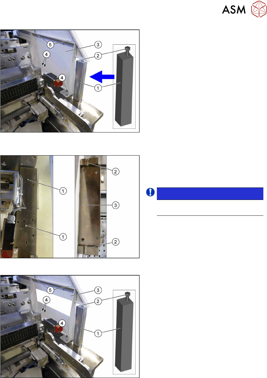
Fig.68: Inserting the support and remove the standard sup-
port frame
► Insert the support [03136824‑xx](1)
between the top side cover and the
machine frame.
► Tighten the screw(2) until the support
is clamped firmly into place.
► Remove the top two screws(5) fasten-
ing the standard support frame(3).
► Remove the bottom four screws(4)
fastening the standard support frame.
► Carefully remove the standard support
frame from the machine.
Fig.69: Knocking in the bolt
► Knock in the two centering pins
[03015816‑xx](1).
These should protrude out of the base
plate by 5mm+/‑0.5mm.
NOTICE!
The cavities(2) on the SIPLACE JTF
support frame(3) are 6mm deep.
.
Fig.70: Fitting the SIPLACE JTF support frame and remov-
ing the support
► Insert the SIPLACE JTF support
frame(3) into the machine.
► Fasten the SIPLACE JTF support
frame at the bottom with four ISO4762-
M8x12-A2-70 [03042583‑xx](4)
screws.
► Fasten the SIPLACE JTF support
frame at the top with two ISO4762-
M6x8-A2-70 [03043124‑xx](5) screws.
► Loosen the screw(2) on the top end of
the support(1) and remove the support
from the machine.
4 Setting up and commissioning
4.2 Retrofitting in the SIPLACE TX-Series
136 User Manual / Bedienungsanleitung / 用户手册 SIPLACE TX V1/V2 Series JEDEC Tray Feeder (JTF-ML2) 11/2019
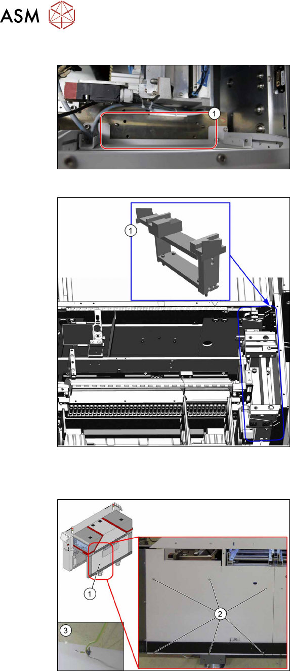
4.2.5.4 Fitting the SIPLACE JTF-ML2 adapter
Fig.71: Cleaning
► Clean the surface(1) with a lint-free
cloth and ethanol before fitting the
SIPLACE JTF-ML2 adapter.
Fig.72: Mounting the SIPLACE JTF-ML2 adapter
► Insert the SIPLACE JTF-ML2 adap-
ter(1) into the machine.
► Fasten the SIPLACE JTF-ML2 adapter
with four ISO4762-M8x35-A2-70
[03042588‑xx] screws.
Use a suitable extension for this.
4.2.5.5 Fitting the machine protective features
Fig.73: Fitting the side cover
► Fasten the ground cable(3).
► Fasten the SIPLACE JTF side cover(1)
with six ISO7380-2M6x8-A2-70
[03099592‑xx](2) screws.