00198439-03_SIPLACE_JTF-ML2_TX12_V1-V2_DE_EN_CHS.pdf - 第147页
4 Setting up and commissioning 4.2 Retrofitting in the SIPLACE TX-Series User Manual / Bedienungsanleitung / 用户手册 SIPLACE TX V1/V2 Series JEDEC Tray Feeder (JTF-ML2) 11/2019 147 Fig.96: Wiring the SIPLACE JTF-ML2 at SIP…
4 Setting up and commissioning
4.2 Retrofitting in the SIPLACE TX-Series
146 User Manual / Bedienungsanleitung / 用户手册 SIPLACE TX V1/V2 Series JEDEC Tray Feeder (JTF-ML2) 11/2019
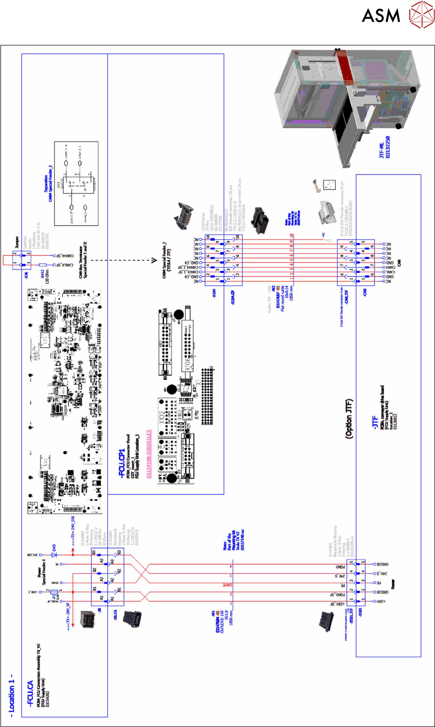
4.2.5.10 Establishing the electrical connections on the SIPLACE TX-Series V2
On the SIPLACE TX V2, use the following cables for this:
●
Cable: JTF Power and 24V_S [03147684-xx]
●
Cable: JTF CAN [03147687-xx]
Also observe the detailed circuit diagrams (see below).
► Dismantle the waste tape chute.
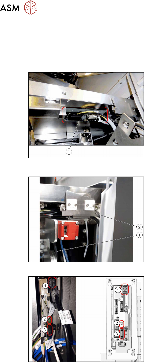
Fig.93: Connector on the SIPLACE JTF-ML2
(SIPLACETXV2)
► (1) Plug in the cables [03134469‑xx]
and [03134468‑xx] at the SIPLACE
JTF‑ML2.
► Run the cables below the conveyor of
the SIPLACE JTF‑ML2 towards the
connecting assembly.
Fig.94: Cable routing (SIPLACE TX V2)
► Pay attention to the correct running of
the cables [03134469‑xx] and
[03134468‑xx](1) at the conveyor. The
cables must be routed behind the re-
taining bracket(2). Do not use the two
sockets.
Fig.95: Cable with docked COT
Connecting assembly:
1. Power cable
2. Glue feeder
3. CAN Bus
► Plug the power cable [03147684‑xx]
into the connector X8 on the FCU.
► Plug the CAN bus cable into the con-
nector X104 of the connecting assem-
bly.
4 Setting up and commissioning
4.2 Retrofitting in the SIPLACE TX-Series
User Manual / Bedienungsanleitung / 用户手册 SIPLACE TX V1/V2 Series JEDEC Tray Feeder (JTF-ML2) 11/2019 147
Fig.96: Wiring the SIPLACE JTF-ML2 at SIPLACE TX series V2 – part 1
4 Setting up and commissioning
4.2 Retrofitting in the SIPLACE TX-Series
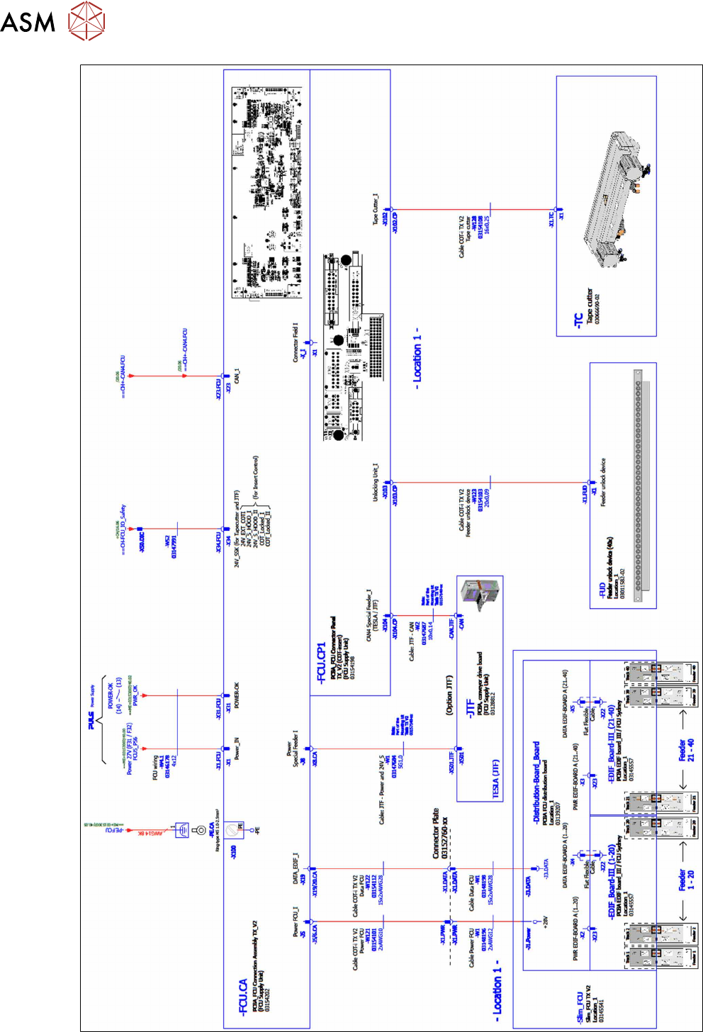
148 User Manual / Bedienungsanleitung / 用户手册 SIPLACE TX V1/V2 Series JEDEC Tray Feeder (JTF-ML2) 11/2019
Fig.97: Wiring the SIPLACE JTF-ML2 at SIPLACE TX series V2 – part 2