00198439-03_SIPLACE_JTF-ML2_TX12_V1-V2_DE_EN_CHS.pdf - 第127页
4 Setting up and commissioning 4.2 Retrofitting in the SIPLACE TX-Series User Manual / Bedienungsanleitung / 用户手册 SIPLACE TX V1/V2 Series JEDEC Tray Feeder (JTF-ML2) 11/2019 127 Fig.44: Removing the empty tape duct ► Re…
4 Setting up and commissioning
4.2 Retrofitting in the SIPLACE TX-Series
126 User Manual / Bedienungsanleitung / 用户手册 SIPLACE TX V1/V2 Series JEDEC Tray Feeder (JTF-ML2) 11/2019
4.2.5 Performing retrofitting
4.2.5.1 Preparatory steps
► Move the component trolleys out of the machine.
► Switch off the machine, disconnect it from the power supply and secure it to prevent
unauthorized reactivation.
4.2.5.2 Converting the COT insert for the SIPLACE TX
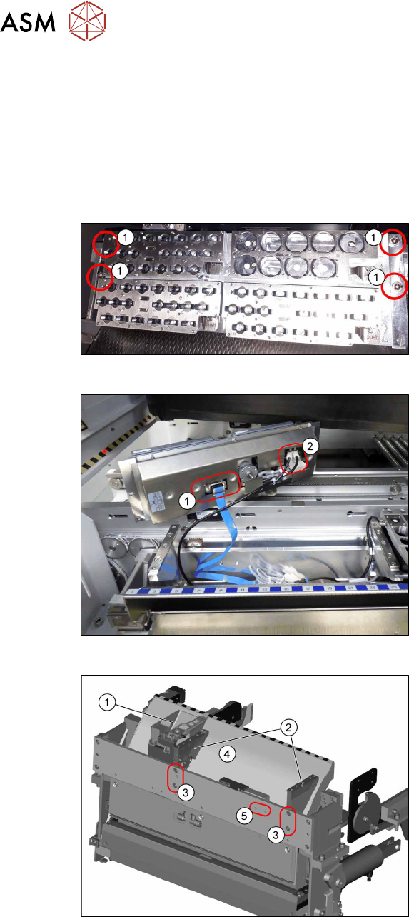
Fig.41: Removing NC 1
► Remove the four screws(1) fastening
the nozzle changer (NC).
Fig.42: Removing NC 2
► Unplug the electrical(1) and pneumatic
connections(2) for the nozzle changer
and put the NC aside.
Fig.43: Removing the NC holder
► Remove the reject bin(1).
► To remove the empty tape duct (4)
remove the screws(3) fastening the
two NC holders(2) and remove the NC
holders.
(The screw holes marked with (5) will be
used for the holder of the big reject bin later
on)
4 Setting up and commissioning
4.2 Retrofitting in the SIPLACE TX-Series
User Manual / Bedienungsanleitung / 用户手册 SIPLACE TX V1/V2 Series JEDEC Tray Feeder (JTF-ML2) 11/2019 127
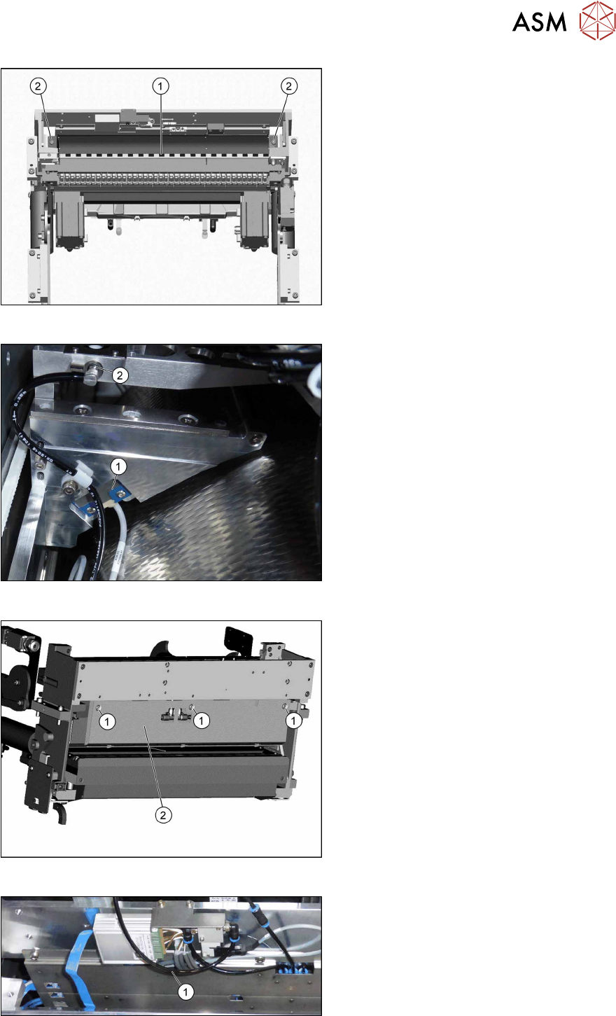
Fig.44: Removing the empty tape duct
► Remove the two screws (2) holding the
empty tape duct (1).
► Carefully lift the empty tape duct out of
the COT insert.
Fig.45: Dismantling the sensor
► Dismantle the sensor(1) on the right
NC holder.
► Dismantle the vacuum hose and extend
it with the adapter assembly nozzle sta-
tion TX V2 [03169973—xx] (2).
► This is necessary if a CPP head and
the big reject bin with nozzle station are
installed.
Fig.46: Dismantling the rear cover
► Remove the three screws(1) fastening
the rear cover(2).
Now, you can move the cover a bit to the
side and lift it off. Thus, it is easier to thread
the sensor cable.
Fig.47: Converting the sensor
► Push the sensor through the open-
ing(1) on the front cover.
4 Setting up and commissioning
4.2 Retrofitting in the SIPLACE TX-Series
128 User Manual / Bedienungsanleitung / 用户手册 SIPLACE TX V1/V2 Series JEDEC Tray Feeder (JTF-ML2) 11/2019
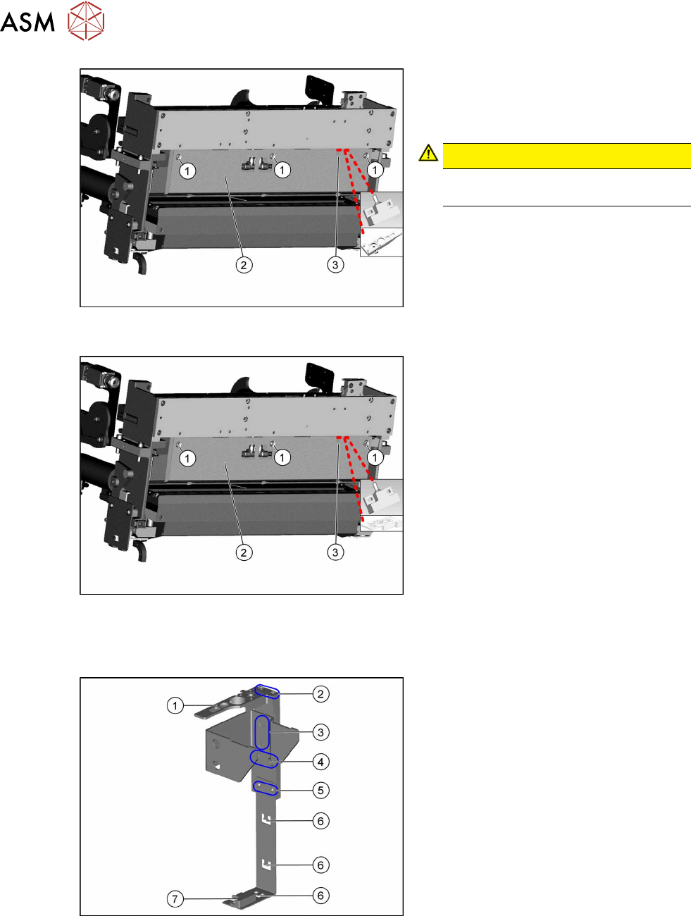
Fig.48: Fitting the rear cover
SIPLACE TX-Series V1
► Fasten the rear cover(2) with three
screws(1).
The sensor cable is run through the
opening(3) in the cover.
CAUTION!
Make sure not to clamp any hoses or
cables.
.
Fig.49: Fitting the rear cover
SIPLACE TX-Series V2
Fitting the reject bin holder with nozzle station for the SIPLACE TX Series V1
Fig.50: Fitting the reject bin holder
1. Nozzle station [03090348‑xx]
The nozzle station is fitted after meas-
uring the height.
2. Fastening screws of the nozzle station
[00333782‑xx]
3. Fastening screws for retaining bracket
ISO10642-M5x10-A2-70 [03082832‑xx]
4. Fastening screws of the complete
holder on the COT insert DIN7984-
M6x12-A2-70 [03081847‑xx]
5. Fastening screws ISO 7380-2 M 3 x 6-
A2-70 [03099571-xx], only for setting
the sensor height
6. Three lugs for cable ties
7. Sensor [03088550‑xx]
The sensor that is already installed and
cabled on the insert is used.
► Fit the individual parts of the reject bin holder.
► Use the cable ties to fix the sensor to the three lugs.