00198439-03_SIPLACE_JTF-ML2_TX12_V1-V2_DE_EN_CHS.pdf - 第143页
4 Setting up and commissioning 4.2 Retrofitting in the SIPLACE TX-Series User Manual / Bedienungsanleitung / 用户手册 SIPLACE TX V1/V2 Series JEDEC Tray Feeder (JTF-ML2) 11/2019 143 Fig.89: Cable routing ► Pay attention to …
4 Setting up and commissioning
4.2 Retrofitting in the SIPLACE TX-Series
142 User Manual / Bedienungsanleitung / 用户手册 SIPLACE TX V1/V2 Series JEDEC Tray Feeder (JTF-ML2) 11/2019
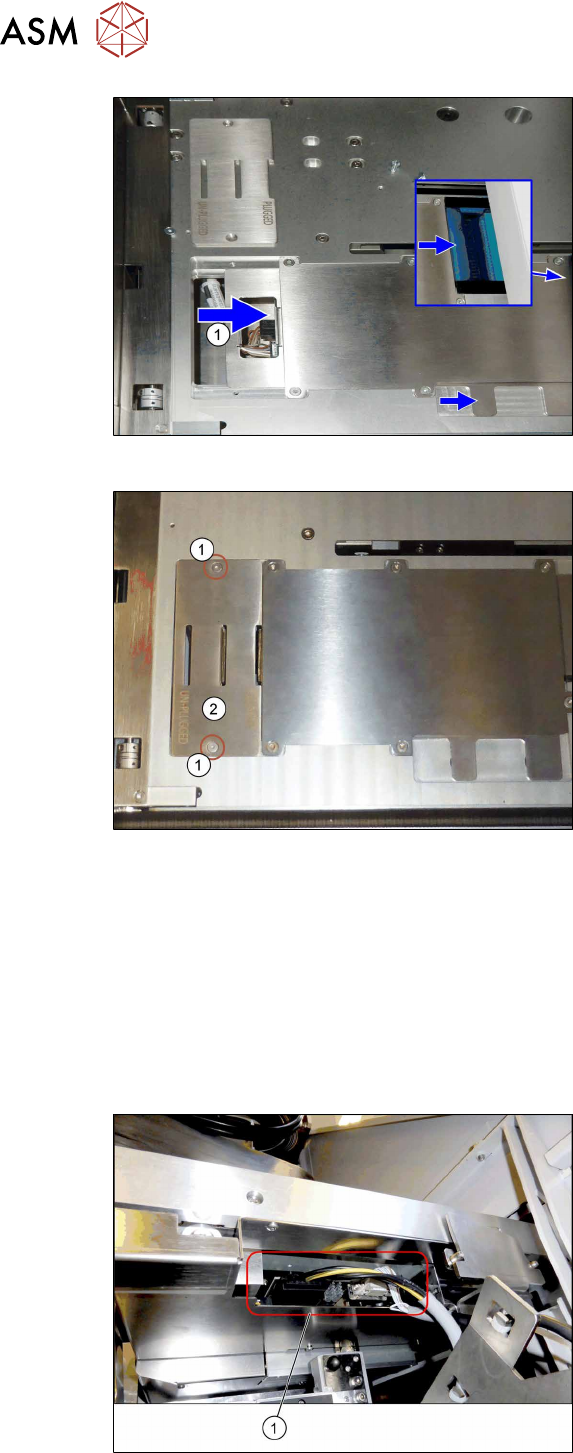
Fig.86: Mounting the conveyor 6
► Push the plate(1) until end position to
the right.
This way the electric connection
between conveyor and tower is estab-
lished (see blue window).
If necessary, hold against the plug on
the tower side for better connection.
Fig.87: Mounting the conveyor 7
► Fit the cover(2) using two screws(1).
4.2.5.9 Establishing the electrical connections on the SIPLACE TX-Series V1
On the SIPLACE TX V1, use the following cables for this:
●
Cable COTi TX: DC control to SIPLACE JTF-ML [03134469‑xx]
●
Cable COTi TX: CAN bus3 to SIPLACE JTF-ML [03134468‑xx]
Also observe the detailed circuit diagrams (see below).
► Remove the cover above the FCU connectors (see also 7.1.1 "Replacing the Feeder Control
Unit (FCU)" [}177]).
Fig.88: Connector on the SIPLACE JTF-ML2
► (1) Plug in the cables [03134469‑xx]
and [03134468‑xx] at the SIPLACE
JTF‑ML2.
4 Setting up and commissioning
4.2 Retrofitting in the SIPLACE TX-Series
User Manual / Bedienungsanleitung / 用户手册 SIPLACE TX V1/V2 Series JEDEC Tray Feeder (JTF-ML2) 11/2019 143
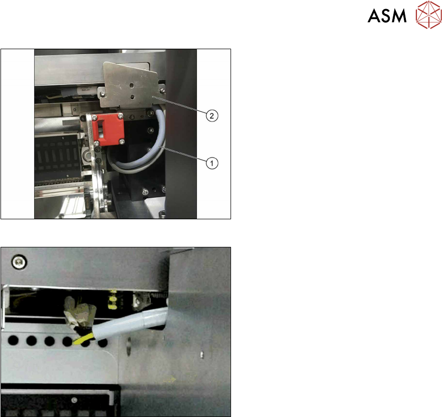
Fig.89: Cable routing
► Pay attention to the correct running of
the cables [03134469‑xx] and
[03134468‑xx](1) at the conveyor. The
cables have to be in the mounting
bracket(2).
Fig.90: Cable with docked COT
► Make sure there is a gap between the
cable and the COT to avoid cable rub-
bing during insertion or removal of
COT.
► Run the cables below the conveyor of the SIPLACE JTF‑ML2 towards the back of the COT
insert.
► Connect the CAN bus cable [03134468‑xx] to connector X17 at the FCU.
► Locate the connectors X1.JTF and X4.COTi1 in the machine base.
► Connect the power cable [03134469‑xx] to connectors X1.JTF and X4.COTi1 at the cable har-
ness. If necessary also use adapter cable [03160347‑xx].
4 Setting up and commissioning
4.2 Retrofitting in the SIPLACE TX-Series
144 User Manual / Bedienungsanleitung / 用户手册 SIPLACE TX V1/V2 Series JEDEC Tray Feeder (JTF-ML2) 11/2019
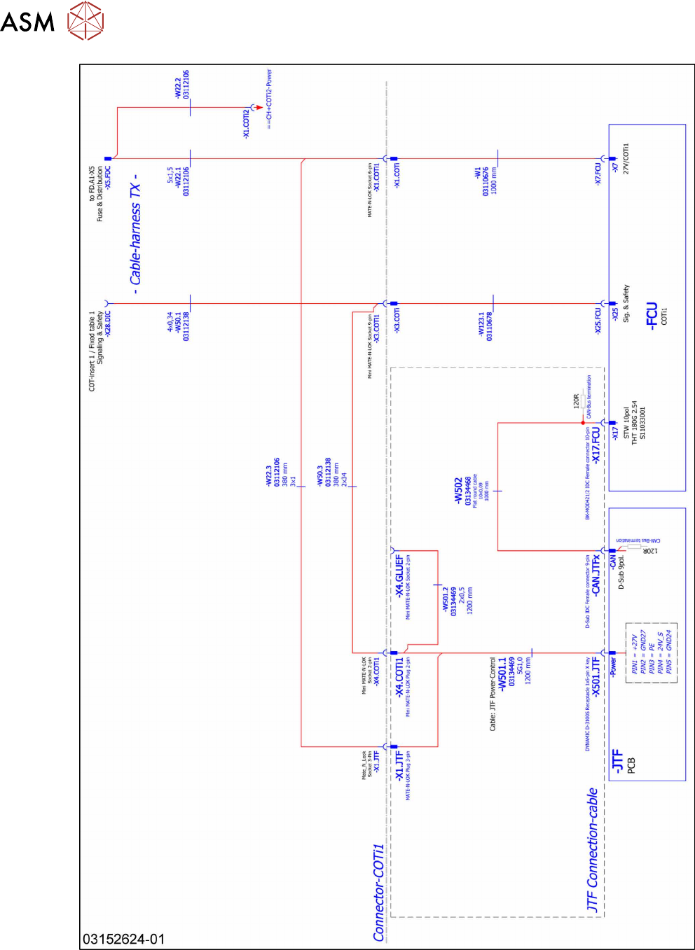
Fig.91: Wiring the SIPLACE JTF-ML2 at SIPLACE TX series V1 – part 1