00198439-03_SIPLACE_JTF-ML2_TX12_V1-V2_DE_EN_CHS.pdf - 第181页
7 Appendix 7.1 Excerpts from the Service Manual User Manual / Bedienungsanleitung / 用户手册 SIPLACE TX V1/V2 Series JEDEC Tray Feeder (JTF-ML2) 11/2019 181 7.1.2 Nozzle Changer Setting 7.1.2.1 Setting the nozzle changer hei…
7 Appendix
7.1 Excerpts from the Service Manual
180 User Manual / Bedienungsanleitung / 用户手册 SIPLACE TX V1/V2 Series JEDEC Tray Feeder (JTF-ML2) 11/2019
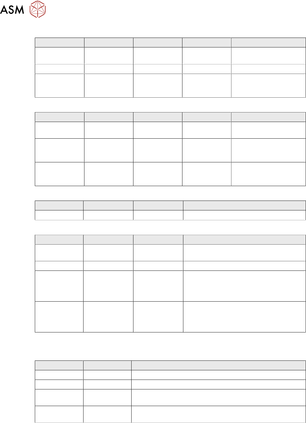
LED (test mode for reject box switched off – S2.1 ON) [03059783-04]
LED Color Result State Signal name Description
H1, H2, H3, H4 GN Sequential shift
light
LED1, 2, 3, 4 FCU OK
H1, H2, H3, H4 GN ON LED1, 2, 3, 4 eSW application missing
H1, H2, H3, H4 GN Flashing LED1, 2, 3, 4 FCU error, reboot place-
ment machine or replace
FCU
LED (test mode for reject box switched on – S2.1 OFF) [03059783-04]
LED Color Result State Signal name Description
H1 or H2 or H3
or H4
GN Flashes LED1 or 2 or 3
or 4
No sensor connected for
reject box 1 or 2 or 3 or 4
H1 or H2 or H3
or H4
GN OFF LED1 or 2 or 3
or 4
Sensor for reject boxes 1
or 2 or 3 or 4 connected
and no reject box inserted
H1 or H2 or H3
or H4
GN ON LED1 or 2 or 3
or 4
Sensor for reject boxes 1
or 2 or 3 or 4 connected
and no reject box inserted
Button S1 [03059783-04]
Button Result State Function Description
S1 OFF RESET When pressed
DIP switch S2 [03059783-04]
Switch Result State Signal name Description
S2.1 ON/OFF FCU_ENV3 ON: test mode for reject box switched off
OFF: test mode for reject box switched on
S2.2 OFF FCU_ENV2 40 fold FCU
S2.3 ON/OFF FCU_ENV1 ON: without insert control, with virtual but-
ton
OFF: with insert control, without virtual but-
ton
S2.4 ON/OFF FCU_ENV0 ON: with tape cutter and with nozzle
changer functionality
OFF: without tape cutter and without nozzle
changer functionality
If an "X-FCU / X-Series" [03059623-xx] is fitted as replacement for an "FCU X-Series" [03020068-
xx] in the "COT insert X-Series" or at the "Docking station for component trolley SIPLACE X", you
need to set the DIP switch as follows:
Switch Result State Comment
S2.1 ON Test mode for reject bin switched off
S2.2 OFF FCU for 40 feed tracks
S2.3 OFF COT insert control with pushbutton / without button GUI (vir-
tual).
S2.4 OFF "HW version 6" meaning without tape cutter and nozzle
changer functionality
7 Appendix
7.1 Excerpts from the Service Manual
User Manual / Bedienungsanleitung / 用户手册 SIPLACE TX V1/V2 Series JEDEC Tray Feeder (JTF-ML2) 11/2019 181
7.1.2 Nozzle Changer Setting
7.1.2.1 Setting the nozzle changer height
Parts, equipment and tools
●
Measuring scale
●
NC shim plate (0.3mm) [03021079-xx]
Overview
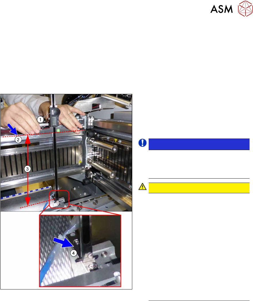
Fig.160: Overview of measurement procedure
1. Measuring scale
2. Top edge of the X axis upper linear
guide
3. Values to be set (277 +/- 0.2 mm)
4. Nozzle changer contact surface
NOTICE!
Alternatively, you can measure from
the top edge of the lower guide rail of
the gantry. In this case the distance is
116.0+/‑0.2mm.
.
CAUTION!
Only with mixed mode option
If applicable, observe the deviating
measurements for the mixed mode op-
tion:
Installation height of NC:
280.65 +/ 0.2 mm
Measured from the upper edge of the
top linear guide
OR
119.65 +/ 0.2 mm
Measured from the upper edge of the
bottom linear guide
See also the assembly instruction
manual "Option Mixed Mode –
SIPLACE TX2i" [00198536‑xx]
.
7 Appendix
7.1 Excerpts from the Service Manual
182 User Manual / Bedienungsanleitung / 用户手册 SIPLACE TX V1/V2 Series JEDEC Tray Feeder (JTF-ML2) 11/2019
Adjustment
DANGER
Strong permanent magnet fields
Observe the safety instructions in section Safety instructions for working with strong mag-
netic fields.
► Remove the nozzle changer.
► During the following inside measurement make sure that the tip of the measuring scale does
not touch the magnetic strip as this might scratch it!
CAUTION
Strong magnetic forces
Place a suitable plastic plate between the magnet and measuring scale, if required.
► Position the measuring scale(1) on the top edge of the X axis upper linear guide(2) and
measure the distance to the nozzle changer contact surface(4).
► Hold the measuring scale vertically.
► The setting value (3) is 277+/‑0.2mm.
(Deviating values for Mixed Mode option, see above.)
You can adjust the height, where necessary, by removing or adding NC shim plates.
CAUTION
Crash hazard!
Do not place too many shim plates underneath.
► Calibrate the position of the nozzle changer.
7.1.2.2 Setting the Nozzle Station Height
Parts, Equipment and Tools
●
Measuring scale
●
Adjusting plates: support for nozzle reject device [03039514-xx]
Setting
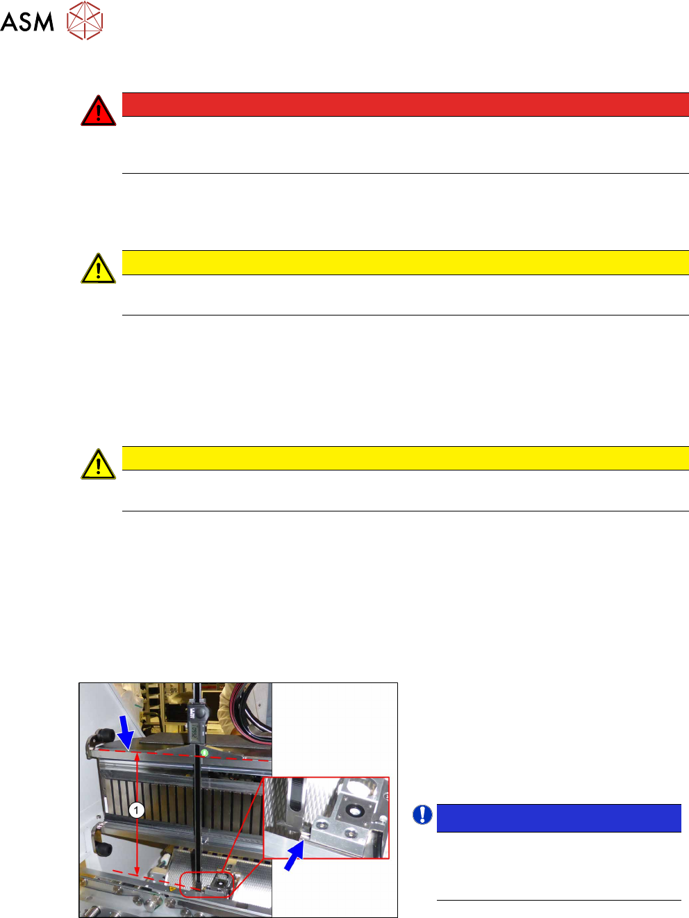
Fig.161: Setting the Height of the Nozzle Station
(taking the standard nozzle station as example)
► The distance(1) between the contact
surface of the nozzle station and the
top edge of the upper guide rail of the
gantry needs to be
266.0+0.1/-0.3mm.
You may need to use shim plates to
adjust this.
NOTICE!
Alternatively, you can measure from
the top edge of the lower guide rail of
the gantry. In this case the distance is
105.0+0.1/-0.3mm.
.