00198382-03_UM_SIPLACE-CA4-V2_EN.pdf - 第108页
3 Technical data and assemblies I nstruction manual SIPLACE CA4 V 2 3.3 Dimensions and weight From s oftware version 713.0 E dition 12/ 2019 108 3.3.3 Maneuvering dist ances for SIPLACE W afer System (SWS) 3 Fig. 3.3 - 5…
Instruction manual SIPLACE CA4 V2 3 Technical data and assemblies
From software version 713.0 Edition 12/2019 3.3 Dimensions and weight
107
3.3.2 For a definition of placement performance values
3
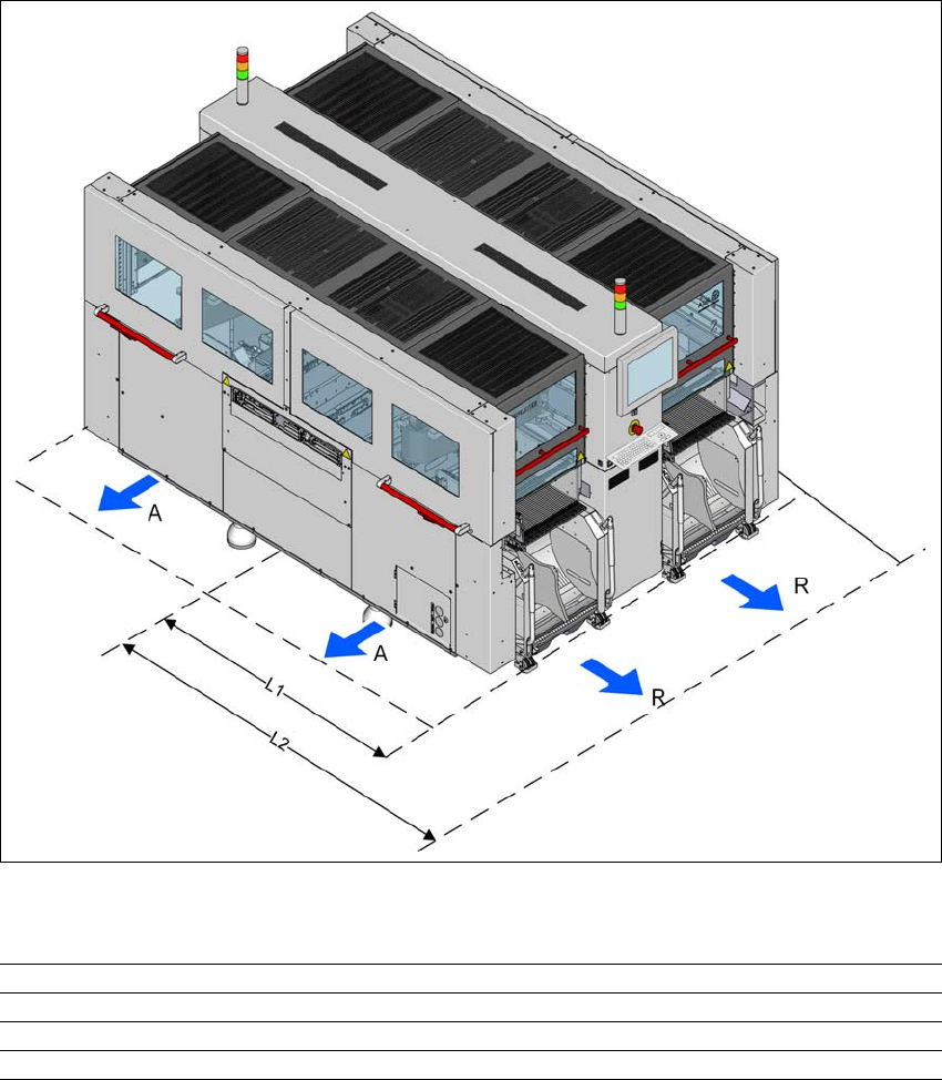
Fig. 3.3 - 4 Maneuvering distances of component trolleys in SIPLACE CA4 V2
3
Working area (A) and minimum distance to the adjacent placement machine 500 mm
Maneuvering distance (R) location position 600 mm
Distance L1: Machine center to outer edge of X component trolley 1470 mm
Distance L2: Machine center to wall 2300 mm
3 Technical data and assemblies Instruction manual SIPLACE CA4 V2
3.3 Dimensions and weight From software version 713.0 Edition 12/2019
108
3.3.3 Maneuvering distances for SIPLACE Wafer System (SWS)
3
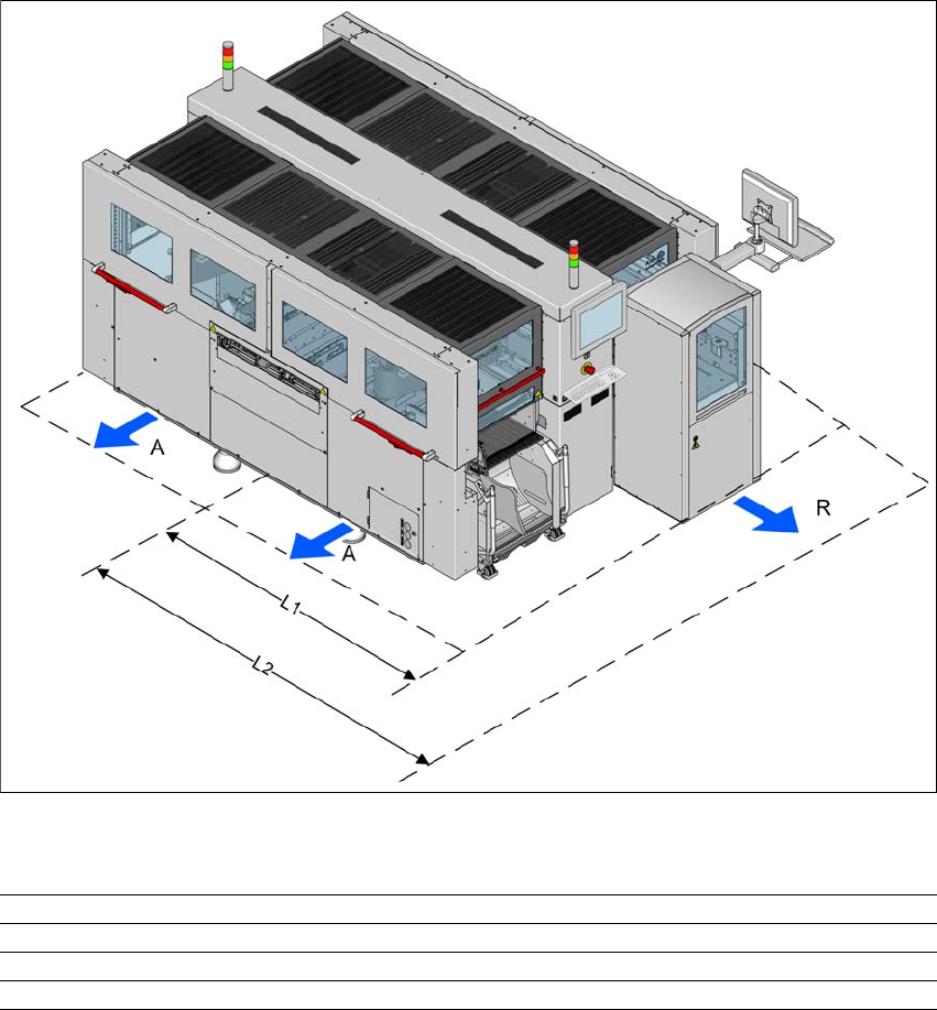
Fig. 3.3 - 5 SWS maneuvering distances at the SIPLACE CA4 V2
3
Working area (A) and minimum distance to the adjacent placement machine 500 mm
Maneuvering distance (R) location position 1000 mm
Distance L1: Machine center to outer edge of SWS 1980 mm
Distance L2: Machine center to wall 2980 mm
Instruction manual SIPLACE CA4 V2 3 Technical data and assemblies
From software version 713.0 Edition 12/2019 3.3 Dimensions and weight
109
3.3.4 Placement machine center of gravity
3
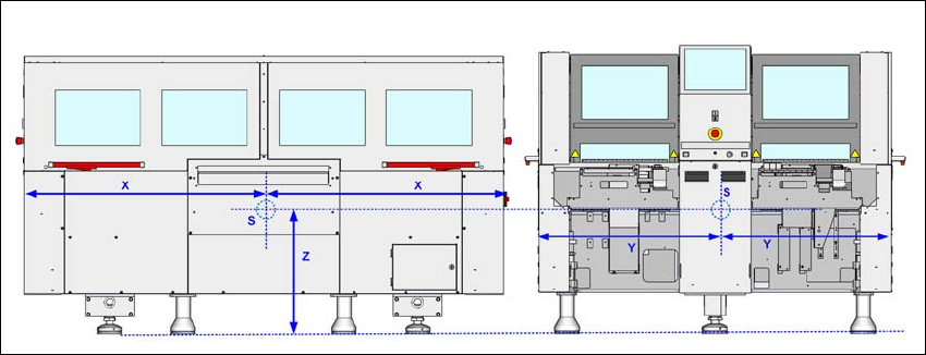
Fig. 3.3 - 6 Placement machine center of gravity in millimeters
X = 100
Y = 1050mm
Z = 630 mm
S = center of gravity
These center of gravity coordinates relate to placement machines with a PCB conveyor height of
930 mm.