00198382-03_UM_SIPLACE-CA4-V2_EN.pdf - 第76页
2 Operational safety Instruction manual SIPLACE CA4 V2 2.6 Safety features From software version 713.0 Edition 12/2019 76 2.6.3.2 Position of the position switches on the pl acement machi ne 2 Fig. 2.6 - 6 Position of po…
Instruction manual SIPLACE CA4 V2 2 Operational safety
From software version 713.0 Edition 12/2019 2.6 Safety features
75
2
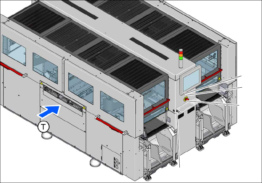
Fig. 2.6 - 5 Position of switches and buttons - location 1/2
(1) Start button (white)
(2) Stop button (black)
(3) EMERGENCY STOP button
(4) Button for docking and undocking the component trolley at the respective location
(T) Direction of PCB conveyor
(3)
(1)
(4)
(2)
2 Operational safety Instruction manual SIPLACE CA4 V2
2.6 Safety features From software version 713.0 Edition 12/2019
76
2.6.3.2 Position of the position switches on the placement machine
2
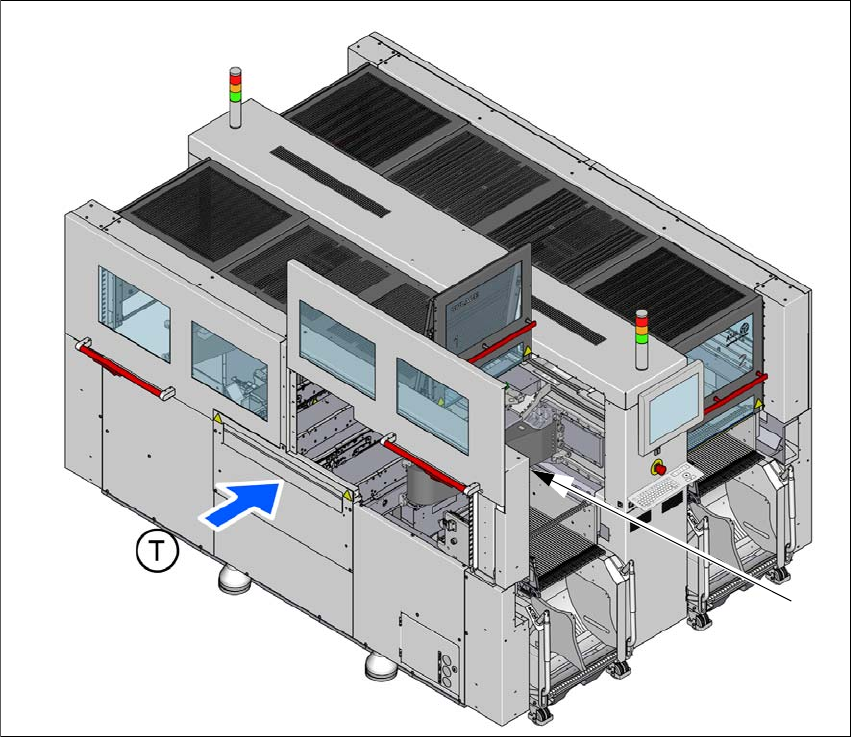
Fig. 2.6 - 6 Position of position switches on the placement machine
(1) Position switch, side sliding door location 1
(2) Position switch, protective cover location 1 (behind item 1)
(T) Direction of PCB conveyor
The position switches for the protective covers and side sliding doors at locations 2 to 4 are iden-
tical as those for location 1.
(1) + (2)

Instruction manual SIPLACE CA4 V2 2 Operational safety
From software version 713.0 Edition 12/2019 2.6 Safety features
77
2.6.3.3 Description of functions
Main switch in OFF position (see item 1 in fig.
2.6 - 4, page 74) 2
The main power switch disconnects the three phases L1, L2, and L3 from the power supply.
2
Main switch in ON position 2
When the main switch is switched to ON, the mains voltage is switched through and all AC/DC
converters are addressed.
The control computer will start and all supply voltages will be made available internally. The inter-
mediate circuit voltages for the gantry axes (300 V-) and star axes (160 V-) plus the supply voltage
for the conveyor drives are also connected via the start button for safety purposes.
Start button, white (item 1 in fig. 2.6 - 4, page 74 and item 1 in fig. 2.6 - 5, page 75) 2
After switching on the main power switch you will be prompted to press the start button in order to
start the placement machine for placement jobs. The same prompt appears if you open the pro-
tective covers or the press the EMERGENCY STOP button.
Press the start button for at least 200 ms, up to a maximum of 1500 ms, and then let go. The
placement machine is switched on when you let go of the button.
Stop button, black (item 2 in fig. 2.6 - 4, page 74 and item 2 in fig. 2.6 - 5, page 75) 2
These buttons are used to stop the placement machine.
DANGER
Incorrect handling of this placement machine can therefore result in death or severe in-
jury or considerable damage to equipment.
The following components still carry potentially lethal voltages even if the main power
switch is switched off:
– Cable connection terminals L1, L2, and L3 of the S1 main power switch
– Main input terminal X94
– Safety cutoff (CSB) still live for approx. 5 minutes after switching off the main switch.
– The color of all individual wires, which still carry electricity, even if the main power
switch is switched off, is orange.
Always follow the applicable accident prevention and DIN regulations (particularly
EN 60204, part 1 or IEC 60204, part 1) and the applicable regulations in your own
country.
The safety door to the power supply must ONLY be opened by appropriately quali-
fied and trained personnel.