00198382-03_UM_SIPLACE-CA4-V2_EN.pdf - 第60页
2 Operational safety Instruction manual SIPLACE CA4 V2 2.3 Classification of camera sys tems From software version 713.0 Edition 12/2019 60 2.3 Classification of camera systems 2.3.1 Classification of the whole machine 2…
Instruction manual SIPLACE CA4 V2 2 Operational safety
From software version 713.0 Edition 12/2019 2.2 Warning labels
59
2.2.15.1 Watch out for fluid splash
2
1 in fig. 2.2 - 15, page 58 (quantity per temperature-controlled vacuum tooling: 2)
2.2.15.2 High temperatures on the temperature-controlled vacuum tooling option DM 300
2
2 in fig. 2.2 - 15, page 58 (quantity per temperature-controlled vacuum tooling: 2)
2
Watch out for fluid splash
Risk of injury from fluid splash when the protective panel is removed.
Make sure that the protective panel is fitted so that no fluid can splash
out of the temperature-controlled vacuum tooling DM 300 option.
Wear protective goggles with side protection.
2
High temperatures on the temperature-controlled vacuum tooling option DM
300
Risk of burns due to high temperatures!
The temperature-controlled vacuum tooling DM 300 option can have high
surface temperatures.
Be careful when touching the parts.
2 Operational safety Instruction manual SIPLACE CA4 V2
2.3 Classification of camera systems From software version 713.0 Edition 12/2019
60
2.3 Classification of camera systems
2.3.1 Classification of the whole machine
2
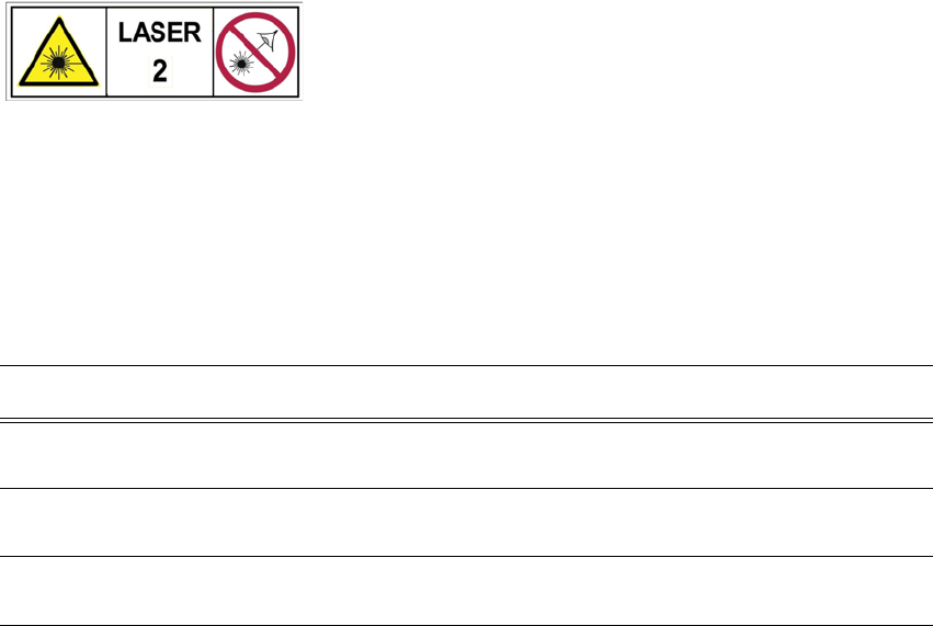
2.3.1.1 Laser classification
The following modules are assigned to risk class 2:
2
The ready-for-operation placement machine is assigned to risk class 2.
The risk classes are determined according to IEC 60825-1:2014.
Assembly Data
Component sensor on SpeedStar Maximum optical output power: < 1 mW
Wavelength: 635 nm
Component sensor on the SIPLACE Multis-
tar CPP
Maximum optical output power: < 1 mW
Wavelength: 635 nm
Laser light barrier on PCB conveyor Maximum optical output power: < 1 mW
Wavelength: 650 nm
Instruction manual SIPLACE CA4 V2 2 Operational safety
From software version 713.0 Edition 12/2019 2.3 Classification of camera systems
61
2.3.2 Classification of the camera systems
2.3.2.1 Camera types with bright LEDs - risk group 1
The bright LEDs are fitted in the following cameras. These are classified as risk group 1, according
to IEC 62741:.
– Component camera type 45 and 49
– PCB camera, type 28
2
2.3.2.2 Camera types with blue LEDs - risk group 2
The ultra-bright blue LEDs are fitted in the following cameras. These are classified as risk group
2, according to IEC 62741:.
– Component camera, type 48
2
2
PLEASE NOTE
Risk group 1
Do not look into the beam of the ready-for-operation camera!
2
Risk group 2
The beam from cameras with ultra-bright blue LEDs can be a haz-
ard.
Do not look into the beam of the ready-for-operation camera!