00198382-03_UM_SIPLACE-CA4-V2_EN.pdf - 第157页
Instruction manual SIPLACE CA4 V2 4 Setting up and commissioning From software version 713.0 Ed ition 12/2019 4.2 Infrastructure at the installation location 157 4.2.3.3 Power supply cable - specification The following c…
4 Setting up and commissioning Instruction manual SIPLACE CA4 V2
4.2 Infrastructure at the installation location From software version 713.0 Edition 12/2019
156
4.2.3.1 Danger notes
4
4
4.2.3.2 Checking the mains power supply
Check whether the power supply complies with the prescribed machine specifications (see table
in section 3.2.3
, page 101).
4
DANGER
Dangerous voltage levels!
The placement machine is supplied with 3 x 380 V~ to 3 x 415 V ± 10 %, 50/60 Hz or op-
tionally with 3 x 200 V~ to 3 x 240 V~ ± 10 %; 50/60 Hz mains voltage. This means that
some parts of the system carry potentially lethal voltages - even when switched off at the
main power switch and with disconnected mains plug.
Incorrect handling of this placement machine can therefore result in death or severe injury
or considerable damage to equipment.
Always follow the applicable accident prevention and DIN regulations (particularly EN
60204, part 1 or IEC 60204, part 1) and the applicable regulations in your own coun-
try.
The covers over the power supply unit may ONLY be opened by appropriately quali-
fied and trained personnel.
DANGER
Lethal voltages under the safety cutoff (CSB) cover!
Under the cover there are components which could still carry lethal voltages, even when
the placement machine is switched off and the mains plug has been disconnected. After
disconnecting the mains plug, wait 5 minutes until the capacitors have discharged.
Never open the covers.
Only ASM Assembly Systems GmbH&Co.KG service engineers or the machine
owner's service engineers, who have been trained by ASM, may perform work on the
power supply and the safety cutoff (CBS).
PLEASE NOTE
Load peaks in power supply
For technical reasons, load peaks occur in the power supply.
Please contact your power company to clarify the mains impedance, if necessary.
Instruction manual SIPLACE CA4 V2 4 Setting up and commissioning
From software version 713.0 Edition 12/2019 4.2 Infrastructure at the installation location
157
4.2.3.3 Power supply cable - specification
The following configurations are possible for the mains connection cable:
(1) Without mains connection cable
(2) 5 x 4 mm² WITH CEE plug; red 16 A (in accordance with IEC 60309),
for 3 x 380 V~ to 3 x 415 V ± 10 %, 50/60 Hz mains voltage
(3) 5 x 4 mm² WITHOUT plug, at 3 x 200 V~ to 3 x 220 V~ ± 10 %; 50/60 Hz or 3 x 380 V~ to 3
x 415 V ± 10 %, 50/60 Hz mains voltage
The color coding for the wires will depend on the country in which the system is operated.
4
4
WARNING
Cross-section and length of mains connection cable
The cross-section and length of the mains connection cable influence the Short-Circuit-
Current-Rating (SCCR) of the placement machine.
When replacing the mains connection cable, do not increase the cross-section of the
wires or shorten the length of the cable.
WARNING
Clear marking of electrical leads!
The electrical leads to each individual placement machine and to the options installed
must be clearly labeled and easily assignable.
The regulations of the country in which the placement machine is operated apply.
4 Setting up and commissioning Instruction manual SIPLACE CA4 V2
4.2 Infrastructure at the installation location From software version 713.0 Edition 12/2019
158
4.2.3.4 Mains connection - WITHOUT mains connection cable (configuration 1)
The placement machine has NO mains connection cable with it on delivery.
4
4
4
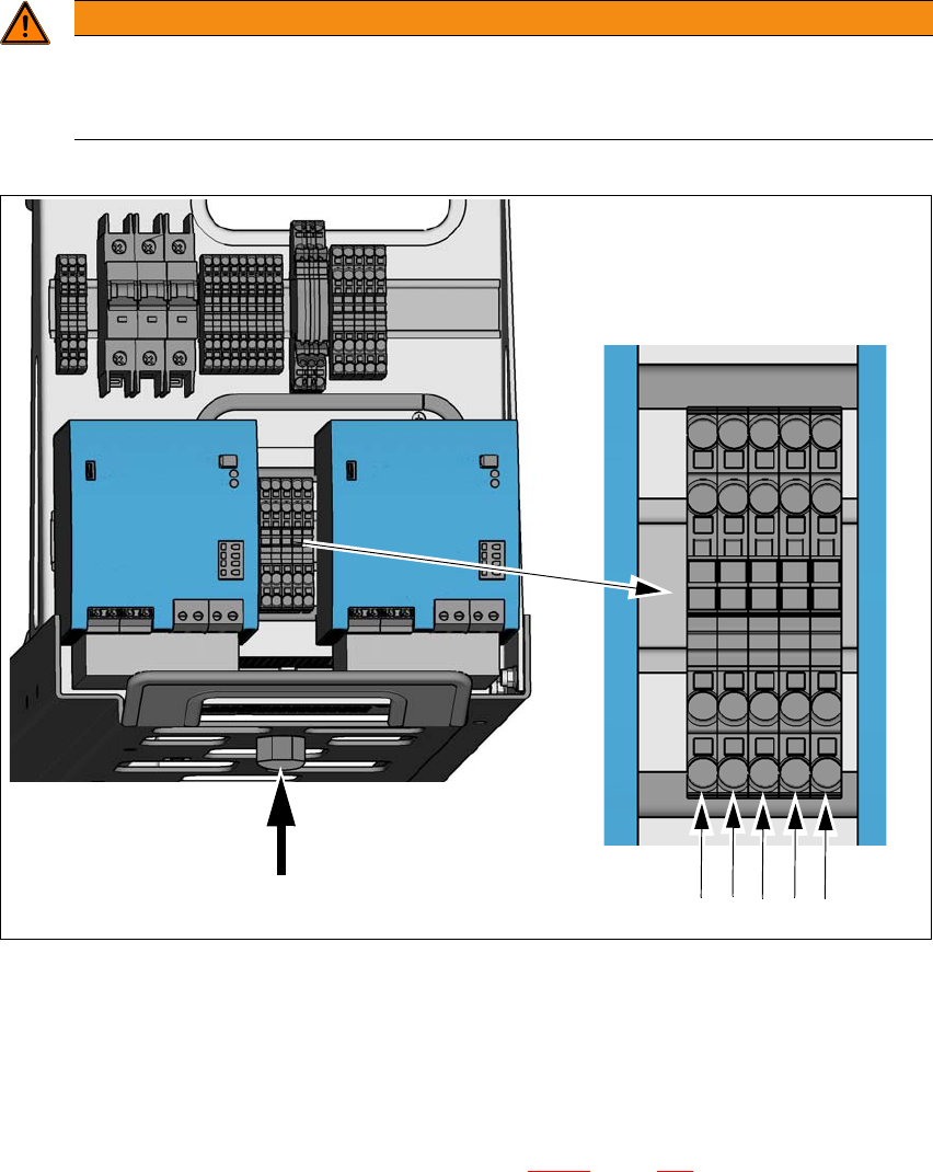
Fig. 4.2 - 4 Terminal panel for connecting the power cable
(1) Mains connection terminals (X94) for the mains power cable L1, L2, L3, N and PE
The connection terminals are designed for a wire diameter of 4 mm².
(2) Opening on the power supply with cable fixture under the power supply
Run the mains connection cable through the cable fixture (item 2) under the power supply to
the main connection terminals X94 (item 1) in fig. 4.2 - 4
, page 158.
Make sure that the bending radius is adequate. The wires must not be kinked.
Crimp a ferrule onto each end of the mains connection cable.
WARNING
The mains connection cable may only be connected by a qualified electrician.
The mains connection cable may only be connected by a qualified electrician.
The regulations of the country in which the placement machine is operated apply.
(2)
(1)
L1 L2 L3 N PE