00198382-03_UM_SIPLACE-CA4-V2_EN.pdf - 第208页
5 Tasks at the placement machine Instruction manual SIPLACE CA4 V2 5.5 The user interface From software version 713.0 Edition 12/201 9 208 The following view will open: 5 Fig. 5.5 - 4 User interface in the "SIPLACE …
Instruction manual SIPLACE CA4 V2 5 Tasks at the placement machine
From software version 713.0 Edition 12/2019 5.5 The user interface
207
5.5.4 Operating the station software in the views
Most views which can be accessed via the toolbar (see section 5.5.3, page 205) have an addi-
tional vertical toolbar with subviews and functions, on the right-hand side of the user interface.
5
Example: View: "Feeder modules, components and nozzles"
Click on "Feeder modules, components and nozzles" in the toolbar.
The following view will open:
5
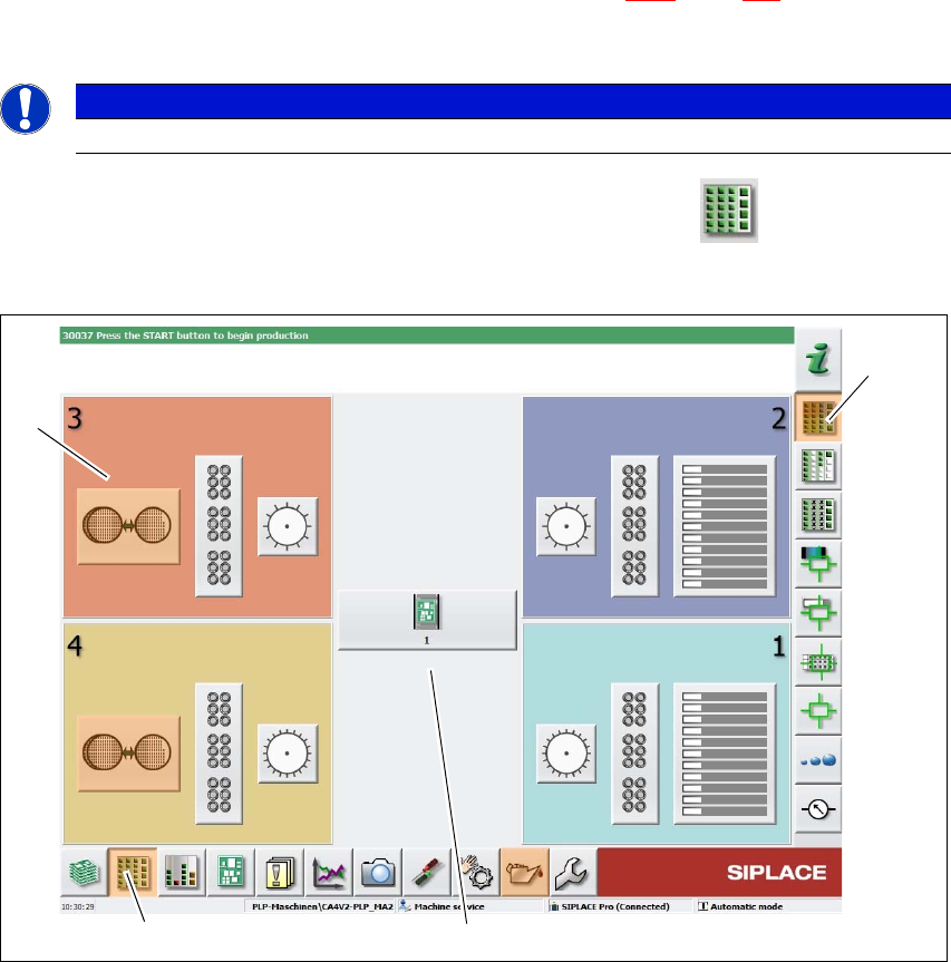
Fig. 5.5 - 3 User interface in the "Feeder module, components and nozzles" view (example)
Legend
(1) Toolbar ("Feeder modules, components and nozzles" button)
(2) Vertical toolbar in "Feeder modules, components and nozzles" view
(3) Processing area with 4 gantries
(4) Button for SIPLACE Wafer System (SWS) at location 3
Click, for example, on the SIPLACE Wafer System (SWS) (4) to open the SWS functions.
PLEASE NOTE
For a detailed description of the individual functions refer to the Online Help.
(1)
(2)
(3)
(4)
5 Tasks at the placement machine Instruction manual SIPLACE CA4 V2
5.5 The user interface From software version 713.0 Edition 12/2019
208
The following view will open:
5
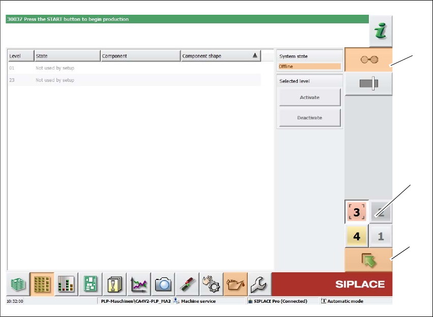
Fig. 5.5 - 4 User interface in the "SIPLACE Wafer System" (example) view
Legend
(1) Vertical toolbar for "SIPLACE Wafer System" functions
(2) Buttons for changing directly to a different gantry
(3) "Up one level" button, to return to previous view (here: "Feeder modules, components and
nozzles" view, see previous diagram)
(1)
(3)
(2)
Instruction manual SIPLACE CA4 V2 5 Tasks at the placement machine
From software version 713.0 Edition 12/2019 5.5 The user interface
209
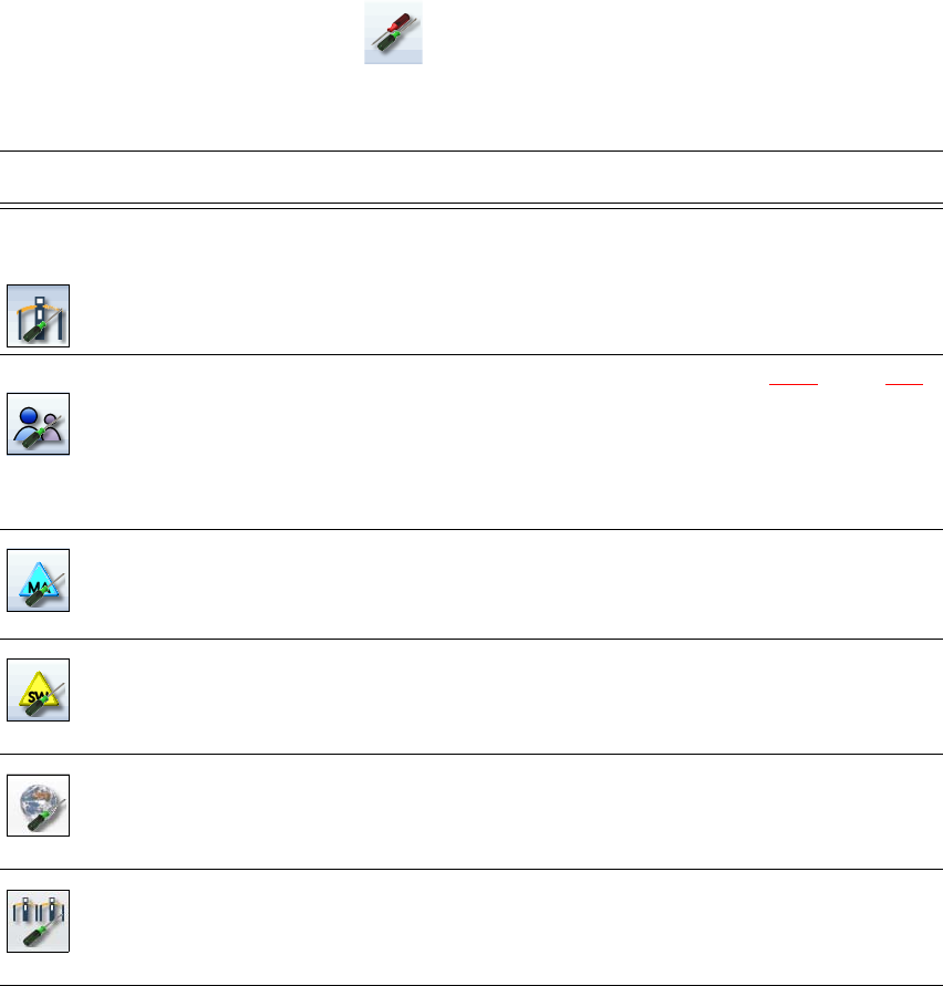
5.5.5 Settings
The "Settings" view allows you to change the various user settings, software options and machine
options.
Click on "Settings" in the toolbar .
The right-hand side shows an additional toolbar. The following table briefly describes the icons
and settings.
Icon Settings Description
Machine settings Only for "Advanced Production" or "Service Customer".
Allows you to set the operating mode and options (e.g. running
options).
Allows you to shut down the machine
Allows you to change over to the operating system.
User Allows you to set the operator level (see section 5.3.2
, page 199).
Allows you to set the language. As a default, English or German
can be selected. A language CD is provided for installation of other
languages.
Further options can be set from the "Advanced production" operator
level.
Machine options No options can be changed in the "Production" level.
Configuration of machine options.
Software options Only for "Service Customer"
Various test functions can be enabled here.
Overview of con-
nected external
systems
Shows all connected external systems (e.g. OIS, SetupCenter).
Shows the connection status and the memory used or deletes the
connected systems.
Adjacent ma-
chines
Display of adjacent machines.