00198382-03_UM_SIPLACE-CA4-V2_EN.pdf - 第118页
3 Technical data and assemblies I nstruction manual SIPLACE CA4 V 2 3.5 Placement head From software version 713.0 Edition 12/2019 118 3.5.4.1 Assembly positions of SIPLACE MultiS tar CPP M The SIPLACE MultiS tar CPP M h…
Instruction manual SIPLACE CA4 V2 3 Technical data and assemblies
From software version 713.0 Edition 12/2019 3.5 Placement head
117
3
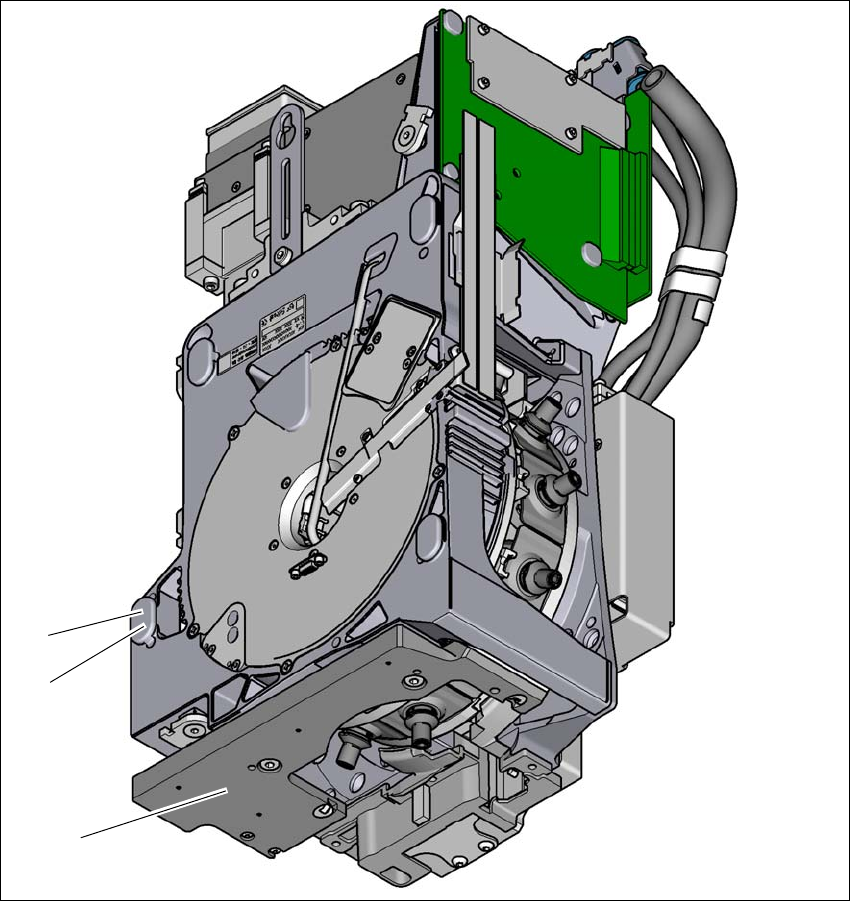
Fig. 3.5 - 4 SIPLACE MultiStar CPP M - rear view, function groups part 3
(1) Component sensor
(2) Assembly position for component height of up to 11.5 mm
(3) Assembly position for component height of up to 6 mm
(3)
(2)
(1)

3 Technical data and assemblies Instruction manual SIPLACE CA4 V2
3.5 Placement head From software version 713.0 Edition 12/2019
118
3.5.4.1 Assembly positions of SIPLACE MultiStar CPP M
The SIPLACE MultiStar CPP M head can be fitted to the head mount in two different positions:
– SIPLACE MultiStar CPP M in the top assembly position (available on request only)
In this position, all components can be processed up to a size of 27 mm x 27 mm and a height
of 8.5 mm. 3
– SIPLACE MultiStar CPP M in the bottom assembly position
In this position, the CPP head places components up to a size of
15 mm x 15 mm and a component height of 6 mm, using the Collect&Place method. 3
Observe the following rules when defining the assembly position:
The head height must be the same for all heads in the same placement area.
3.5.4.2 Classification of component range to be processed
3
3.5.4.3 Placement modes for the SIPLACE MultiStar CPP M
The SIPLACE Multistar CPP M head functions with different placement modes, which vary ac-
cording to the component class. The setup optimization selects the placement mode with the
shortest cycle times. The following table shows the correlation between component class and
placement mode.
Tab. 3.5 - 2 Relations between component class and placement modes
Component
class
Component
size
Assembly
position
*a
of CPP
head
Component
height
Component
camera type
Small compo-
nent
01005 -
15 mm x 15 mm
Top Up to 8.5 mm
Head camera,
type 45
Bottom Up to 6.0 mm
Tab. 3.5 - 1Classification of component range to be processed
*)a Please observe the rules for assembly position heights in section 3.5.4.1
, page 118.
Placement mode Component class
Small component Medium sized
component
Large component
Collect&Place mode Yes No No
Advanced
Pick&Place mode
Yes Yes No

Instruction manual SIPLACE CA4 V2 3 Technical data and assemblies
From software version 713.0 Edition 12/2019 3.5 Placement head
119
3.5.4.4 Assembly positions of SIPLACE Multistar CPP M head in the placement machines
Placement machine Assembly
position
*a
MultiStar CPP M
Maximum component
height
Vision camera
SIPLACE CA4 V2 Bottom 6.0 mm Head camera
Top
*b
8.5 mm Head camera
Tab. 3.5 - 3Assembly positions of SIPLACE Multistar CPP M head in the placement machines
*)a Please observe the rules for assembly position heights in section 3.5.4.1
, page 118.
*)b Only available on request.