00198382-03_UM_SIPLACE-CA4-V2_EN.pdf - 第199页
Instruction manual SIPLACE CA4 V 2 5 Tasks at the placement machi ne From software version 713.0 Ed ition 12/2019 5.3 Switching the SIP LACE CA4 V2 on 199 5.3 Switching the SIPLACE CA4 V2 on 5.3.1 What to consider befo r…

5 Tasks at the placement machine Instruction manual SIPLACE CA4 V2
5.2 Controls and displays From software version 713.0 Edition 12/2019
198
5.2.2 Description
All the controls can be reached by a 1.40 m tall person.
Main switch 5
The main power switch is used to switch the power supply to the placement machine on and off.
5
Stop button, black 5
This black button is used to stop the placement process at the placement machine.
Start button (white) 5
This white button starts the placement machine after it has been switched on or after faults have
been eliminated.
EMERGENCY STOP button 5
The EMERGENCY STOP button latches in the ON position when pressed. The power supply to
the gantry axes, the component trolleys, conveyors and used tape cutters is interrupted and the
voltage supplied to the star axes of the placement heads is reduced. Turn the button to release it.
LCD touchscreen 5
There is a flat LCD screen with a touch-sensitive surface (touchscreen) on either side of the place-
ment machine.
Keyboard 5
The keyboard is located beneath the monitor.
Indicator lamp with buzzer - three color 5
The sequence of colors of the indicator lamps is red - yellow - green. These lamps are used to
signal operating statuses and malfunctions of the placement machine. See also Section 5.7 on
page 215.
DANGER
Lethal voltages!
Some parts inside the placement machine carry potentially lethal voltages - even when
switched off at the main power switch. See also section 2.6.3.3
, page 77.

Instruction manual SIPLACE CA4 V2 5 Tasks at the placement machine
From software version 713.0 Edition 12/2019 5.3 Switching the SIPLACE CA4 V2 on
199
5.3 Switching the SIPLACE CA4 V2 on
5.3.1 What to consider before switching on the stations
5
Check whether the stations are connected to the power and compressed air supplies.
Perform a sight check of the stations. Make sure that there are no obstacles in the travel
range of the gantries.
Make sure that the Z axes of all heads are in their uppermost end positions.
5.3.2 User classification
Certain functions or menus may only be executed or can only accessed by specially trained per-
sonnel. A differentiation is made between the following operator levels:
– Production
– Advanced production
– Service (customer)
The operator levels "Advanced production" and "Service (customer)" can be password protected.
For a detailed description of the user classification, refer to section 5.1
, page 193.
5.3.3 Switching on the station and starting the station software user interface
Switch the station on at the main power switch.
After switching on, check whether the manometers show the required operating pressure.
The station computer software is loaded and the "Production" view of the station software is
shown for the "Production" operator level (see following diagram).
CAUTION
Before you switch on the stations, please perform the following steps.
5 Tasks at the placement machine Instruction manual SIPLACE CA4 V2
5.3 Switching the SIPLACE CA4 V2 on From software version 713.0 Edition 12/2019
200
5
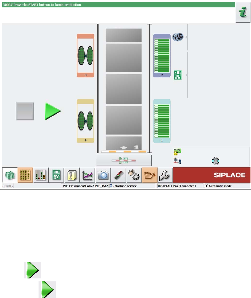
Fig. 5.3 - 1 "Production" view after loading the station software (example)
The status field (see section 5.5.1, page 204) shows the current status of the station and the action
to be performed.
Press the start button when you see the request "Press Start button".
The start buttons are located on the control panels at the left and right of the station.
A reference run will be performed. After the reference run has been completed, the station is
ready for operation and will wait for production data or for printed circuit boards.
The icon will be shown in the working area of the user interface (enabled).
Press the icon to start production.